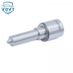
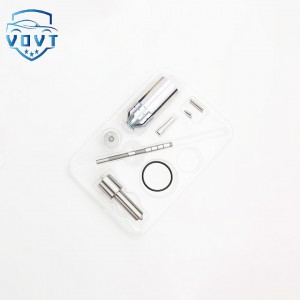
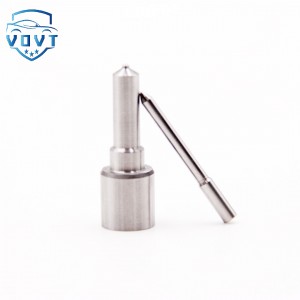
New High Quality Diesel Nozzle DLLA152PN009 105017-0090 for Injection Nozzle Diesel Engine Parts
Products Description
| Reference. Codes | DLLA152PN009 |
| Application | / |
| MOQ | 12PCS |
| Certification | ISO9001 |
| Place of Origin | China |
| Packaging | Neutral packing |
| Quality Control | 100% tested before shipment |
| Lead time | 7~15 working days |
| Payment | T/T, L/C, Paypal, Western Union, MoneyGram or as your requirement |
Research on key technologies, performance optimization and development trends of fuel injector nozzles
I. Introduction
Amid the global push for energy conservation, emission reduction, and improved energy efficiency, engine technology continues to innovate, with precise control of fuel injection systems becoming a key breakthrough. The injector nozzle, the "last checkpoint" for precisely injecting fuel into the engine's combustion chamber, bears the heavy responsibility of atomizing the fuel, distributing the fuel volume, and controlling injection timing. Even small improvements in its performance can significantly impact overall engine performance. From traditional fuel-powered engines to emerging hybrid and even hydrogen-fueled engines, injector nozzles play an indispensable role, continuously driving engine development towards higher efficiency and cleaner operation.
II. Injector Nozzle Structure and Operating Principle
2.1 Basic Structural Components
The injector nozzle structure is sophisticated and complex, typically consisting of core components such as a needle valve, needle valve body, spring, armature, and solenoid coil:
The needle valve and needle valve body form a high-precision mating pair with extremely tight clearances, typically in the micron range (3-5μm). The needle valve reciprocates linearly within the valve body. The pintle at its head precisely mates with the spray hole in the valve body, controlling the opening and closing of fuel injection. The needle valve's shape and dimensions play a decisive role in the atomization and spray direction of the fuel spray. For example, parameters such as the pintle length and cone angle of a pintle valve affect the penetration distance and spray cone angle of the fuel spray.
The spring provides closing force for the needle valve, ensuring a tight fit between the needle valve and the valve body during non-injection periods to prevent fuel leakage. The spring's stiffness and preload are carefully calibrated to ensure reliable closing and responsive opening of the needle valve under various operating conditions. In high-pressure common rail systems, the spring withstands high pressure, and its fatigue life is directly related to the operational stability of the injector nozzle.
The armature and solenoid: When energized, the solenoid generates a magnetic field that attracts the armature, driving the needle valve upward to overcome the spring force and open the spray hole. The mass and kinematic characteristics of the armature affect the injector nozzle's response time. Lightweight and high-permeability armature materials help improve response speed. The number of turns, wire diameter, and winding method of the electromagnetic coil determine the strength and characteristics of the magnetic field it generates, which in turn affects the opening speed of the needle valve and the duration of fuel injection.
2.2 Operational Process Analysis
The operating process of a fuel injector nozzle can be divided into three key stages:
Opening Phase: When the engine control unit (ECU) issues an injection command, current rapidly flows into the electromagnetic coil, generating a strong electromagnetic force. Under this electromagnetic force, the armature drives the needle valve upward, overcoming the spring force, opening the spray hole and ejecting high-pressure fuel from the nozzle at high speed. This phase requires rapid response to ensure precise start of fuel injection. Typically, the opening time must be controlled within 0.3-0.8ms. Slow opening speeds can cause injection delays, disrupting the normal combustion process and reducing engine power output and fuel economy.
Injection Phase: After the needle valve opens, fuel is continuously injected under high pressure. During the injection process, parameters such as fuel flow rate, pressure, and injection angle are determined by the injector nozzle's structural design and the ECU's control strategy. For example, in a high-pressure common rail system, fuel pressure within the common rail can reach as high as 100-300 MPa. Precise control of the needle valve's lift and opening timing enables precise adjustment of the fuel injection quantity. Different engine operating conditions (such as idling, acceleration, and full load) require varying fuel injection quantities and patterns, requiring flexible adjustment of the injector nozzles under ECU control.
During the closing phase, the ECU de-energizes the solenoid coil, dissipating the magnetic field. The needle valve rapidly retracts under spring force, closing the injection port. This closing phase also requires rapid response to prevent fuel leaks, typically requiring a closing time of less than 0.5 ms. Delayed or incomplete closing can result in continued fuel injection outside the combustion chamber, resulting in fuel waste, increased carbon deposits, and even adversely affecting engine operation and emissions.
III. Key Technical Indicators and Influencing Factors
3.1 Fuel Injection Accuracy
Fuel injection accuracy is a core indicator of injector nozzle performance, encompassing both injection quantity accuracy and injection timing accuracy.
Injection quantity accuracy is affected by a variety of factors, including the clearance between the needle valve and the valve body, the dimensional accuracy of the nozzle orifice, fuel pressure stability, and the control accuracy of the solenoid coil. Excessive clearance can lead to fuel leakage, causing the actual injection quantity to fall below the set value. Deviations in nozzle orifice dimensions can alter the fuel flow area, affecting injection quantity. Research has shown that a deviation in nozzle diameter of ±0.01mm can result in a deviation in injection quantity of up to ±5%. In high-pressure common rail systems, high-precision machining processes and advanced pressure control technology can achieve injection quantity accuracy within ±1%.
Injection timing accuracy is primarily determined by the response speed of the solenoid coil, the motion characteristics of the needle valve, and the control accuracy of the ECU. Parameters such as the solenoid coil's inductance and resistance affect its current rise and fall times, which in turn influence the needle valve's opening and closing timing. Needle valve quality, spring stiffness, and lubrication conditions also affect injection timing. The use of a fast-response solenoid coil and optimized needle valve structure, combined with precise ECU control algorithms, enables injection timing accuracy of ±0.5° C (crankshaft angle).
3.2 Atomization Performance
Good atomization performance is key to achieving complete fuel combustion:
Atomized particle size: The structure and size of the nozzle orifice significantly influence the atomized particle size of the fuel. A smaller nozzle orifice diameter allows the fuel to be more easily broken into small droplets under high pressure, but excessively small nozzles are prone to clogging. For example, using a micro-pore (0.1-0.2mm diameter) fuel injector nozzle can achieve an average atomized fuel particle size of 10-20μm, significantly improving atomization performance compared to traditional nozzles (0.2-0.4mm diameter). Furthermore, increasing injection pressure also helps reduce atomized particle size. In a high-pressure common rail system, increasing injection pressure from 100MPa to 200MPa reduces atomized particle size by approximately 30%. Spray cone angle: This is determined by the needle valve head shape and nozzle arrangement. A suitable spray cone angle ensures even fuel distribution within the combustion chamber and thorough mixing with the air. For example, in direct injection engines, the spray cone angle is generally between 60° and 120°, with the specific value optimized based on the combustion chamber geometry and air flow characteristics. A spray cone angle that is too large or too small will result in uneven mixing of fuel and air, affecting combustion efficiency and emissions performance.
3.3 Durability and Reliability
Fuel injector nozzles operate in harsh environments of high temperature, high pressure, and high speed, placing extremely high demands on their durability and reliability.
Material Selection: The needle valve and needle valve body are typically constructed of high-hardness, high-wear-resistant alloys, such as tungsten- and molybdenum-containing alloy steels. Through quenching, tempering, and surface nitriding, the surface hardness can reach HV900-1200, effectively improving wear resistance. For fuel injector nozzles operating in high-temperature environments, the thermal stability of the material must also be considered. For example, key components should be constructed of high-temperature alloys capable of withstanding temperatures of 300-500°C. Wear and Corrosion: Impurities, moisture in the fuel, and acidic substances in combustion products can cause wear and corrosion of the injector nozzles. Wear at the nozzle orifice increases the nozzle diameter, affecting injection volume and atomization performance. Corrosion between the needle valve and the valve body can disrupt their precise fit, leading to leakage. Optimizing the fuel filter's filtration accuracy to reduce impurity ingress and adding anti-corrosion additives to the fuel can effectively reduce wear and corrosion, extending the life of the injector nozzles. Surface coating technologies, such as chrome plating and nickel-phosphorus alloy plating, can also improve surface hardness and corrosion resistance.
IV. Applications in Different Engine Types
4.1 Conventional Fuel Engines
4.1.1 Diesel Engines
In diesel engines, the performance of the injector nozzle significantly impacts the combustion process and emissions characteristics:
High-Pressure Common Rail System: For example, a heavy-duty truck diesel engine utilizes a high-pressure common rail injector nozzle capable of injection pressures of 180-200 MPa. By precisely controlling injection timing, quantity, and pattern (e.g., employing a multi-stage injection strategy with pilot, main, and post-injection), efficient fuel combustion is achieved. In this system, the injector nozzles utilize a micro-pore design (diameter 0.15-0.2mm). Combined with high injection pressure, this results in finer fuel atomization and more thorough mixing with air, effectively reducing nitrogen oxide (NOx) and particulate matter (PM) emissions. Compared to traditional mechanical injection systems, the use of high-pressure common rail injectors reduces engine fuel consumption by 10%-15%, NOx emissions by 30%-40%, and PM emissions by 40%-50%.
Pump-nozzle system: Some small diesel engines utilize a pump-nozzle system, where the injector nozzles are integrated directly into the engine cylinder head and driven directly by the camshaft. This system offers a compact design and high injection pressures (up to 200-250 MPa). However, since the camshaft directly drives the needle valve, higher requirements are placed on the needle valve's motion characteristics and reliability. To improve system performance, high-strength needle valve materials and an optimized cam profile design are used to ensure stable injector operation under high-frequency reciprocating motion. In practical applications, this system demonstrates excellent power and fuel economy in small agricultural machinery, generator sets, and other applications.
4.1.2 Gasoline Engines
Gasoline engine injectors differ from diesel engines in terms of technical characteristics and application requirements:
Multi-point electronic fuel injection systems: In traditional multi-point electronic fuel injection gasoline engines, the injector nozzles are mounted on the intake manifold and inject fuel into the intake duct to mix with the air. The injection pressure is relatively low, typically between 0.2 and 0.3 MPa. To meet the fuel requirements of different engine operating conditions, the injector nozzle's flow characteristics and injection angle are carefully designed. For example, during idling, the injector nozzle sprays a small amount of fuel at a specific injection angle to ensure uniform mixing of fuel and air, maintaining stable engine operation. During acceleration, the injection amount is rapidly increased to ensure engine power output. By optimizing the injector nozzle structure and control strategy, multi-point electronic fuel injection engines achieve a good balance between fuel economy and emissions control.
Direct injection systems: With the advancement of engine technology, direct injection gasoline engines are becoming increasingly popular. Direct injection injectors spray fuel directly into the combustion chamber at high injection pressures, reaching 10-35 MPa. This injection method places higher demands on the injector nozzle's injection accuracy, atomization performance, and response speed. For example, a high-performance direct injection gasoline engine utilizes a multi-hole injector nozzle (6-8 nozzles) with nozzle diameters ranging from 0.1-0.15 mm. At high engine speeds, this allows for extremely fast fuel injection and atomization, achieving stratified and lean combustion, and improving engine thermal efficiency and power performance. Compared to traditional multi-point electronic fuel injection engines, direct injection engines can reduce fuel consumption by 8%-12% and increase power output by 10%-15%. 4.2 New Energy Engines
4.2.1 Hybrid Engines
In hybrid vehicle engines, fuel injectors must adapt to frequent engine starts and stops and switching between different operating modes:
P2 architecture hybrid engines: Taking a P2 architecture hybrid vehicle as an example, the engine frequently switches between pure electric and hybrid drive modes. Under these operating conditions, the injectors must not only ensure efficient injection performance during normal engine operation but also respond quickly and maintain stability during frequent engine starts and stops. To address this challenge, springs with high fatigue resistance and optimized electromagnetic control strategies are employed. In actual use, precise control of the injectors enables accurate fuel injection at the moment of engine start, quickly achieving stable operation. Furthermore, the injection quantity and timing can be rapidly adjusted during switching between different operating modes, ensuring smooth power output and fuel economy. Compared to conventional engines, this hybrid engine reduces fuel consumption by 20%-30% in urban driving. Extended-Range Hybrid Engines: Extended-Range Hybrid Engines primarily function as power generators. Their operating conditions are relatively stable, but they place extremely high demands on fuel economy and power generation efficiency. In this application scenario, fuel injectors utilize high-precision flow control technology and optimized spray characteristics to achieve efficient fuel combustion. For example, intelligent control algorithms adjust the injector's fuel quantity and injection timing in real time based on information such as battery charge and vehicle driving conditions, ensuring the engine always operates within its optimal efficiency range. In actual operation, these extended-range hybrid engines achieve a 10%-15% improvement in power generation efficiency compared to conventional engines, effectively extending the vehicle's range.
4.2.2 Hydrogen Fuel Engines
As a key development direction for future new energy engines, hydrogen fuel engines place new demands on fuel injectors:
Hydrogen Injection Characteristics: The physical properties of hydrogen differ significantly from those of conventional fuels, with its low density and rapid diffusion. Therefore, hydrogen fuel engine injectors require specialized design to ensure precise hydrogen injection and optimal mixing with air. Currently, there are two main methods: low-pressure injection and high-pressure injection. Low-pressure injection generally occurs in the intake manifold, with injection pressures ranging from 0.5 to 1 MPa. By optimizing the injection angle and position of the injector nozzle, hydrogen is thoroughly mixed with air during the intake process. High-pressure injection directly injects hydrogen into the combustion chamber, with injection pressures reaching 30 to 70 MPa, enabling more precise injection control and improved mixing.
Material and Sealing Requirements: Due to the high permeability of hydrogen, extremely high requirements are placed on the materials and sealing properties of injector nozzles. Key components of the injector nozzle must be made of materials that are resistant to hydrogen embrittlement and have excellent sealing properties, such as special alloys and high-performance rubber seals. Furthermore, the structural design must ensure that hydrogen does not leak during injection, ensuring safe engine operation. In actual research and development, through continuous optimization of materials and structures, the reliability and durability of hydrogen-fueled engine injector nozzles have been gradually improved, laying the foundation for the commercial application of hydrogen-fueled engines.


