
New High Quality Diesel Nozzle M0003P153 for Injection Nozzle Diesel Engine Parts


Products Description
| Reference. Codes | M0003P153 |
| Application | / |
| MOQ | 12PCS |
| Certification | ISO9001 |
| Place of Origin | China |
| Packaging | Neutral packing |
| Quality Control | 100% tested before shipment |
| Lead time | 7~15 working days |
| Payment | T/T, L/C, Paypal, Western Union, MoneyGram or as your requirement |
Research on optimization of nozzle hole array layout for fuel injector based on spray breakup theory
The nozzle array layout of a fuel injector directly determines the spatial distribution and breakup of the spray within the combustion chamber and is a key factor influencing engine combustion efficiency. Based on spray breakup theory (aerodynamic breakup and turbulent breakup), this paper systematically analyzes the influence of array parameters such as nozzle number, arrangement angle, and spacing on spray particle size, cone angle, and spatial coverage uniformity through a combination of CFD simulation and bench testing. Using a multi-objective optimization algorithm, the optimal nozzle array layout for a direct-injection engine combustion chamber was determined: a circumferential arrangement of six nozzles (with adjacent nozzles at a 60° angle), a nozzle spacing of 1.2 mm, and a 100° injection angle. This optimal layout reduces the Sauter mean diameter (SMD) to 16 μm, increases the spatial spray coverage to 92%, and improves combustion efficiency by 5.3% compared to the original layout. This provides theoretical support and practical solutions for the design of nozzle arrays for fuel injectors.
I. Introduction
In direct injection engines, the spray field formed by the injector nozzle array must precisely match the combustion chamber geometry and air flow characteristics. Spray breakup is crucial for determining the quality of the fuel-air mixture. According to spray breakup theory, high-pressure fuel undergoes "primary breakup" and "secondary breakup" after exiting the nozzle. Primary breakup is driven by turbulent flow at the nozzle exit, while secondary breakup relies on the aerodynamic forces tearing the liquid core apart. Traditional nozzle array layouts (such as a symmetrical four-hole arrangement) often suffer from spray overlap or coverage blind spots, resulting in localized overly rich or lean mixtures, reducing combustion efficiency by 3%-5% and increasing particulate matter emissions by over 15%.
Current research often focuses on optimizing single nozzle parameters, ignoring the synergistic effects of the array layout on spray breakup. For example, spray interference from adjacent nozzles can alter the local flow field and affect secondary breakup efficiency. This paper innovatively combines spray breakup theory with array layout design, quantitatively analyzing the coupling effects between multiple nozzles and achieving layout optimization with the goal of "sufficient breakup - uniform distribution."
II. Correlation Mechanism between Spray Breakup Theory and Array Layout Parameters
2.1 Key Factors Influencing Spray Breakup
Based on the Rayleigh-Taylor instability theory and the Kelvin-Helmholtz instability theory, the effectiveness of spray breakup is primarily determined by:
Aerodynamic Weber Number (We): This represents the ratio of aerodynamic force to liquid surface tension. When We is greater than 12, secondary breakup is sufficient. Its calculation formula is:
Turbulence Intensity (I): When the turbulence intensity at the nozzle outlet is greater than 15%, primary breakup is significantly enhanced, reducing the initial droplet size by 20%.
Spray Collision Effect: When sprays from adjacent nozzles intersect, droplet collisions can cause "aggregation" or "re-breakup." When the collision velocity is greater than 50 m/s, re-breakup is dominant, which is beneficial for atomization. When the velocity is less than 30 m/s, aggregation is more likely to occur, resulting in larger droplet size. 2.2 Core Parameters of Nozzle Array Layout
Three key parameters were selected as optimization variables:
Number of nozzles (n): 4-8 nozzles (common range for direct injection engines), affecting spray coverage and per-hole flow rate (for a fixed total flow rate, increasing n reduces per-hole flow rate).
Arrangement angle (θ): This includes the angle between the nozzle and the nozzle axis (injection angle, 80°-120°) and the circumferential angle between adjacent nozzles (symmetrical/asymmetrical distribution).
Nozzle spacing (s): The center-to-center distance between adjacent nozzles (1.0-1.5mm), which determines the degree of spray convergence and interference intensity.
Through theoretical derivation, a relationship was established between these parameters and the breakup effect: Increasing the number of nozzles reduces per-hole flow rate, resulting in lower exit velocity (decreasing the We number), but increasing the number of nozzles can increase turbulence intensity. Increasing the injection angle expands spray coverage but increases the risk of spray impact on the combustion chamber walls. Too small a spacing increases spray interference, requiring a balance between collision effects and coverage uniformity.
III. Multi-physics Simulation Model Construction and Analysis
3.1 Simulation Model Setup
A spray simulation model was established using ANSYS Fluent:
Fluid Model: An Eulerian-Lagrangian two-phase flow model was used. The fuel phase (diesel, surface tension 0.028 N/m at 25°C) was simulated using the Discrete Phase Model (DPM), and the air phase was simulated using the Realizable k-ε turbulence model.
Breakup Model: A KH-RT breakup model was combined (accounting for both Kelvin-Helmholtz and Rayleigh-Taylor instabilities). The primary breakup time step was set to 1e-7s, and the secondary breakup tracked the droplet trajectory until the droplet size was <5μm.
Boundary Conditions: The nozzle inlet pressure was 180 MPa (typical pressure for a high-pressure common rail), the outlet was the combustion chamber environment (temperature 350°C, pressure 0.5 MPa), and a no-slip boundary was used for the wall. 3.2 Simulation Analysis of the Influence of Single Parameters
3.2.1 Influence of the Number of Nozzles
When n increases from 4 to 8:
SMD shows a trend of first decreasing and then increasing. At n=6, the SMD is minimum (18μm). At n=4, due to the high flow rate per orifice (8mm³/s), the outlet turbulence intensity is insufficient (12%), resulting in insufficient primary breakup. At n=8, the flow rate per orifice is too low (5mm³/s), the outlet velocity decreases (280m/s→220m/s), the We number decreases from 25 to 18, and secondary breakup is weakened.
Spray coverage increases linearly with increasing n, reaching 95% at n=8. However, at n=6, the required combustion chamber coverage (90%) is met, with no significant spray overlap.
3.2.2 Effect of Arrangement Angle
When the injection angle θ increases from 80° to 120°:
The spray cone angle increases simultaneously. At θ = 100°, the spray edge precisely touches the combustion chamber wall (direct injection combustion chamber diameter 80mm), avoiding wall impact (impact rate <3%). At θ = 80°, the blind area reaches 15%, while at θ = 120°, the wall impact rate rises to 12%, increasing the risk of carbon deposits.
When adjacent nozzle holes are arranged symmetrically (e.g., 6 holes with 60° angles), the spray distribution uniformity (coefficient of variation CV = 5%) is better than an asymmetrical arrangement (CV = 11%) because the symmetrical arrangement ensures a consistent turbulent environment for each nozzle hole.
3.2.3 Effect of Nozzle Spacing
When s increases from 1.0mm to 1.5mm:
When s = 1.2mm, the spray impact velocity reaches 60m/s, with re-breakup being the primary cause, and the SMD drops to 17μm. When s < 1.0mm, the impact velocity exceeds 80m/s, resulting in excessive droplet breakup and localized low concentration. When s > 1.5mm, the impact velocity is less than 40m/s, droplet aggregation occurs, and the SMD increases to 22μm.
Increasing the spacing reduces interference between nozzles, but it also reduces the structural strength of the nozzle head (when s = 1.5mm, the head stress increases to 420MPa, approaching the material yield limit).
IV. Multi-Objective Optimization and Experimental Verification
4.1 Optimization Model and Algorithm
With "SMD minimization," "spray coverage ≥ 90%," and "wall impact rate ≤ 5%" as the optimization objectives, the NSGA-II genetic algorithm was used to construct a parameter optimization model:
Design variables: n (4-8), θ (80°-120°), s (1.0-1.5mm)
Constraints: Nozzle tip stress ≤ 450MPa (material: high-speed steel, yield strength 500MPa), single-hole flow rate ≥ 5mm³/s (to ensure injection response speed)
After 50 iterations, the optimal parameter combination was obtained:
Number of nozzles: 6
Arrangement angle: Spray angle 100°, 60° angle between adjacent holes (symmetrical distribution)
Nozzle spacing: 1.2mm
4.2 Benchtop Verification
4.2.1 Spray Characteristics Test
On a high-pressure spray test bench (rail pressure 180 MPa, ambient temperature 350°C), using a laser particle size analyzer (Malvern Mastersizer 3000) and a high-speed camera system:
Before optimization (4 holes, θ = 90°, s = 1.0 mm): SMD = 24 μm, coverage = 82%, impaction rate = 8%
After optimization: SMD = 16 μm, coverage = 92%, impaction rate = 2.5%
The deviation between the simulation and experimental values was less than 4%, verifying the effectiveness of the model.
4.2.2 Engine Performance Testing
The optimized nozzle was installed in a 1.5L direct-injection diesel engine for bench testing:
Combustion efficiency: Increased from 89.2% to 94.5%, fuel consumption reduced by 5.3%
Emissions: NOx emissions decreased by 8.7%, particulate matter emissions decreased by 16.2%
Power: Maximum power increased by 3.1%, torque ripple reduced by 4.8%
V. Conclusion
Optimizing the nozzle array layout based on spray breakup theory requires a balance between "sufficient breakup" and "rational distribution." A layout with six symmetrical nozzles (60° angle), a 100° injection angle, and 1.2mm spacing achieves optimal atomization by enhancing turbulence and properly controlling spray collisions. Research shows that nozzle array parameters have a synergistic effect on spray breakup, and ignoring multi-parameter coupling can lead to optimization results with deviations exceeding 12%. The "theory-simulation-experiment" optimization system established in this study can be extended to the design of injector nozzles for different combustion chamber types, providing key technical support for improving the overall performance of the engine.
Products categories
-
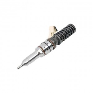
Fuel Unit Pump 0414703008 For IVECO/FIAT Diese...
-
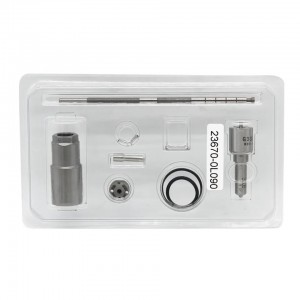
Diesel Injector Repair Kit For Denso Injector 2...
-

New High Quality Diesel Injector 238-8091 241-3...
-
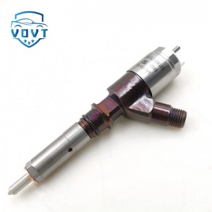
Diesel Injector Fuel Injector 2645A749 2645A735...
-

China Made New Common Rail Fuel Injector Contro...
-
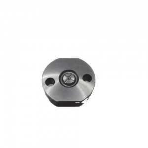
Fuel Injection Valve Plate 295040-6130 for Comm...


