
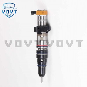
New High Quality Diesel Injector 4W-3563 6I-3075 0R-8680 7C-0345 7C-2239 For CAT 3500A


Products Description
| Reference. Codes | 3500A |
| Application | 3500A |
| MOQ | 4PCS |
| Certification | ISO9001 |
| Place of Origin | China |
| Packaging | Neutral packing |
| Quality Control | 100% tested before shipment |
| Lead time | 7~10 working days |
| Payment | T/T, L/C, Paypal, Western Union, MoneyGram or as your requirement |
How to optimize the design of the injector to improve its flow characteristics?
1. Optimization of spray hole structure
1. Design of spray hole geometric parameters
Diameter and number
Small diameter multi-spray hole: Reducing the diameter of a single spray hole and increasing the number of spray holes can improve the quality of fuel atomization (smaller oil droplet size), while expanding the fuel distribution range through multi-path injection, which is especially suitable for the stratified combustion requirements of direct injection (GDI) engines. For example, reducing the spray hole diameter from 0.3mm to 0.15mm, combined with 6-8 spray holes, can reduce the fuel atomization particle size by more than 30%, while maintaining the flow output by increasing the total flow area.
Variable cross-section spray hole: Using a "convergent-divergent" type spray hole (such as a Laval nozzle structure), using the critical velocity principle in fluid mechanics, a high-speed jet is formed at the throat of the spray hole, reducing the fuel wall effect and improving flow stability.
Nozzle angle and injection cone angle
The nozzle angle is optimized according to the shape of the combustion chamber and the direction of airflow (such as vortex and tumble) to match the fuel jet with the intake vortex, avoid direct impact of the fuel on the piston top or cylinder wall, and reduce the wet wall phenomenon. For example, in a turbocharged direct injection engine, the nozzle angle is usually designed to be 60°-90° to match the compact combustion chamber layout.
2. Nozzle surface treatment
Nano coating technology: Diamond-like carbon (DLC) or silicon nitride (Si₃N₄) coating is applied to the inner wall of the nozzle to reduce surface roughness (Ra<0.2μm), reduce fuel flow resistance, and improve wear resistance and corrosion resistance. Experiments show that coating treatment can increase the injector flow coefficient (actual flow/theoretical flow) by 5%-8%, and reduce the flow attenuation rate by 40% after long-term use.
Rounding of the nozzle edge: Precisely round the nozzle inlet and outlet edges (R=0.01-0.03mm) to eliminate turbulence and cavitation caused by sharp angles and avoid flow fluctuations caused by fuel bubble aggregation.
2. Internal flow channel optimization
1. Valve system structure design
Low inertia needle valve: Use lightweight needle valve (such as hollow structure or titanium alloy material) to reduce motion inertia and shorten opening/closing delay (response time < 0.5ms). For example, piezoelectric injectors directly drive needle valves through piezoelectric ceramics. Compared with traditional electromagnetic injectors, the response speed is increased by more than 50%, which can achieve more accurate short pulse (such as less than 0.1ms) flow control.
Double spring structure: Set the main spring and auxiliary spring to act in stages under different injection pressures to avoid needle valve oscillation (such as water hammer effect) and ensure flow stability under low flow conditions (such as idling).
2. Flow channel smoothness and volume control
Flow channel polishing process: electrochemical polishing or laser polishing of the fuel flow channel inside the injector (such as the pressure chamber and the fuel inlet hole) to make the surface roughness Ra < 0.4μm, reduce fuel turbulence and pressure loss. For example, a high-pressure common rail injector reduces the flow fluctuation rate from ±3% to ±1.5% at an injection pressure of 200MPa through flow channel polishing.
Optimize the pressure chamber volume: reduce the pressure chamber volume, reduce the impact of fuel compressibility, and make the pressure response faster when the needle valve is opened. For example, reducing the pressure chamber volume from 0.8mm³ to 0.3mm³ can shorten the injection delay time by 0.2ms, which is especially suitable for multiple injection strategies (such as pre-injection + main injection + post-injection).
3. Optimization of materials and manufacturing processes
1. High temperature and wear resistant materials
Needle valve and valve seat: Silicon nitride ceramics (hardness HV1800-2200) or tungsten carbide (hardness HV1300-1500) are used to improve the ability to resist oil erosion and wear and extend the service life. For example, after 1 million injections, the wear of the ceramic needle valve is less than 5μm, while the wear of the traditional stainless steel needle valve can reach more than 20μm.
Seal material: Fluororubber (FKM) or perfluororubber (FFKM) is selected to withstand high temperatures (above 250℃) and fuel erosion, avoiding leakage or flow deviation caused by seal failure.
2. Precision manufacturing and assembly
Spray hole processing technology: Laser drilling (accuracy ±2μm) or electrospark machining (EDM) is used to ensure the consistency of the spray hole diameter, position and angle (tolerance ±0.5°). For example, a fuel injector manufacturer has reduced the nozzle angle error from ±1.5° to ±0.3° through five-axis laser processing technology, and improved the flow uniformity of each nozzle to within ±2%.
Dynamic flow calibration: After assembly, each fuel injector is subjected to dynamic flow testing (such as flow scanning under different pulse widths and pressures), and individual differences are compensated through software correction (such as the fuel injector characteristic table in the ECU) to achieve flow consistency of batch products (deviation <±1.5%).
4. Drive and control strategy optimization
1. High-speed response drive technology
Piezoelectric drive vs. electromagnetic drive: Piezoelectric injectors use the inverse piezoelectric effect of piezoelectric ceramics to achieve nanosecond response, which is suitable for high-frequency, short-pulse injection (such as more than 5 injections per cycle); electromagnetic injectors shorten the opening delay from 1.2ms to less than 0.6ms by optimizing the coil inductance (such as using a flat coil to reduce internal resistance) and the permanent magnet structure.
Pulse Width Modulation (PWM) Optimization: Adopting adaptive PWM control algorithm, the drive current waveform (such as pre-excitation current + holding current mode) is adjusted in real time according to the fuel temperature and injection pressure to ensure the dynamic stability of the needle valve opening/closing process. For example, during low-temperature cold start, the pre-excitation current peak is increased (from 8A to 12A), the needle valve opening delay is shortened, and the insufficient flow caused by the increase in fuel viscosity is compensated.
2. Multi-stage injection strategy
Pre-injection + main injection: A small dose of pre-injection (such as 5-10mg/cycle) is performed 0.5-1ms before the main injection to reduce combustion noise and nitrogen oxide (NOx) emissions. At the same time, the pre-injection cleans the nozzle hole and reduces the impact of carbon deposit blockage on flow characteristics.
Post-injection control: A small amount of post-injection (such as 2-5mg/cycle) is performed in the late stage of combustion, and the high-temperature gas is used to further atomize the fuel, optimize hydrocarbon (HC) and particulate matter (PM) emissions, and the fuel is used to flush the nozzle surface to inhibit carbon deposit growth.
5. Simulation and test verification
1. CFD fluid simulation
Use tools such as ANSYS Fluent or STAR-CCM + to perform numerical simulation on the internal flow field of the injector and analyze the fuel flow rate, pressure distribution and cavitation phenomenon under different working conditions. For example, by optimizing the transition fillet between the pressure chamber and the nozzle through simulation, the cavitation area can be reduced by 25%, avoiding flow fluctuations and nozzle erosion caused by cavitation.
2. Bench test and engine matching
Flow characteristic test: On the injector test bench, test the actual flow under different injection pressures (such as 50-300MPa), pulse widths (0.2-20ms) and temperatures (-40℃-120℃), draw a flow characteristic MAP diagram, identify the working points with large flow deviations (such as small pulse width and low pressure areas), and adjust the structural parameters in a targeted manner.
Engine dynamic matching: Perform full-operation condition (idle, partial load, full load, acceleration/deceleration) tests on the engine bench, verify the influence of injector flow characteristics on air-fuel ratio, combustion efficiency and emissions through emission analyzer and cylinder pressure sensor, and iteratively optimize design parameters (such as spray hole angle, drive pulse width).
Products categories
-

Auto Parts Fuel Injector Diesel Injection 178-0...
-

Excavator Parts C15 injectors 211-3025 Fuel Inj...
-

New High Quality Diesel Injector 7E-3384 0R-305...
-
New High Quality Diesel Injector 10R4763 387-94...
-

New High Quality Diesel Injector 212-3468 10R-1...
-

New High Quality Diesel Injector 20R-8057 20R-8...


