
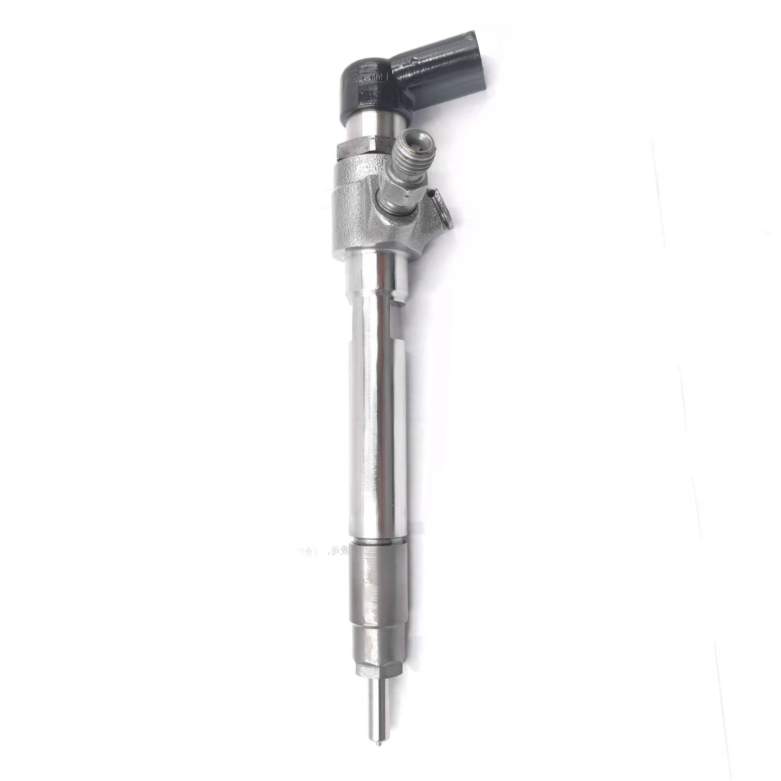
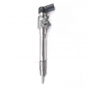
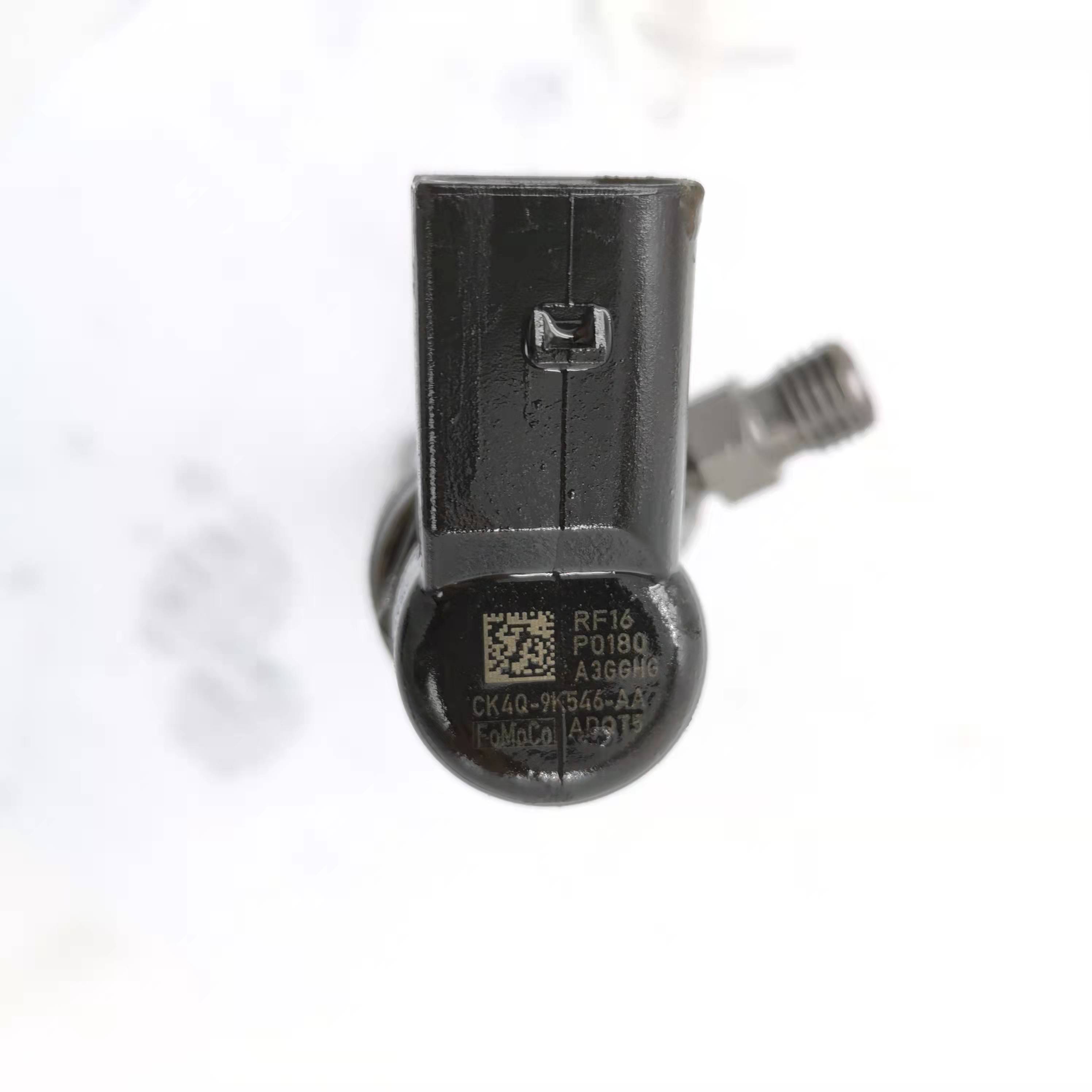
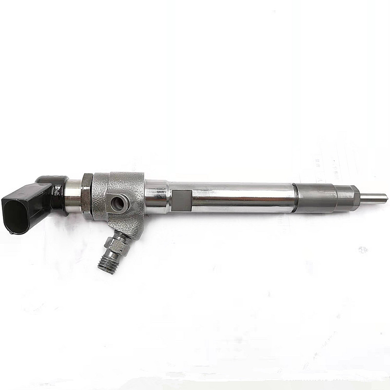
Diesel Injector Fuel Injector A2c59515264 Siemens for Ford Ranger 3.0L Engine


products detail
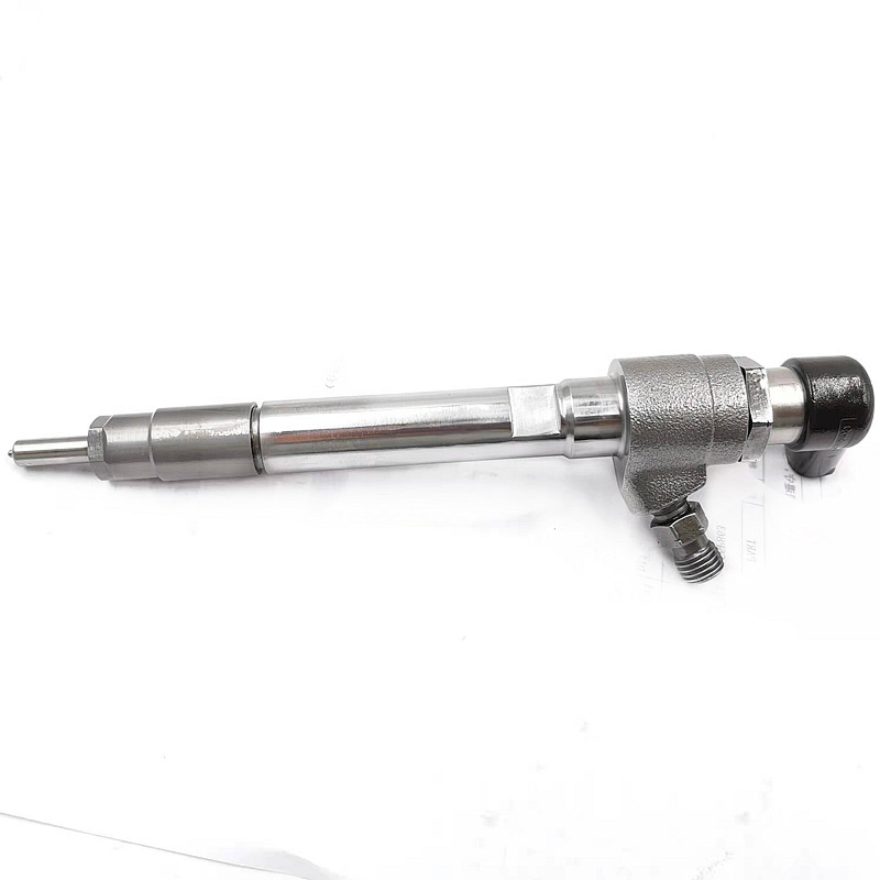

Used in Vehicles / Engines
| Product Code | A2c59515264 |
| Engine Model | / |
| Application | Ford Ranger |
| MOQ | 6 pcs / Negotiated |
| Packaging | White Box Packaging or Customer's Requirement |
| Warranty | 6 months |
| Lead time | 7-15 working days after confirm order |
| Payment | T/T, PAYPAL, as your preference |
| Delivery Method | DHL, TNT, UPS, FedEx, EMS or Requested |
FAQ
Simulation Study on the Impact of Uneven Fuel Injection of Each Hole of the Diesel Engine Injector on the Combustion Process (PART 3)
2 Combustion model
The geometric model of the combustion chamber at TDC (top dead center) is drawn by ProE software, as shown in Figure 1, and it is saved as a STEP format file. The geometric model is imported into hyper mesh software for mesh division and saved as a mesh file in the form of NAS. The mesh file is imported into AVL FIRE software for mesh inspection, refinement, dynamic mesh setting, selection of sub-models and parameter setting [6].
The 4-hole injector adopted by the F186 diesel engine has 4 evenly-distributed holes, but the injection direction is inconsistent with the angle of the cylinder section. The center of the pit of the ω combustion chamber has a 3 mm offset from the center of the piston, and the airflow movement in cylinder has different impact on the fuel sprays of each hole, so the whole combustion chamber modeling is adopted. The mesh is encrypted in the area close to the hole and the boundary, and the mesh model at TDC is shown in Figure 2. There are 140448 and 343488 mesh cells at TDC and BDC (bottom dead center) respectively.
The parameters of the diesel engine are shown in Table 1. The position and direction settings of the injector are as follows: X-coordinate (0.003 m), Y-coordinate (-0.003 m), Z-coordinate (0 m), X-direction (0.007), Y-direction (0.0397), Z-direction (0). The position setting of each hole is shown in Table 2. The uniform injection rate and measured uneven injection rate of each hole are made as the injection setting, and the injection rate is shown in Figure 3. The standard component transport model of diesel fuel is used for chemical reaction kinetics calculation, and the calculation model involved is shown in Table 3 [7, 8].
Products categories
-

High Quality New Diesel Injector CAT C9 Common ...
-

High Quality Diesel Injector 0445110418 0 445 1...
-

High Quality New Diesel Injector RE533501 BEBE4...
-

High Quality New Diesel Injector 28232251 R2823...
-

Auto Parts Fuel Injector Diesel Pump Injector 0...
-

New High Quality Diesel Injector 387-9439 20R-8...


