
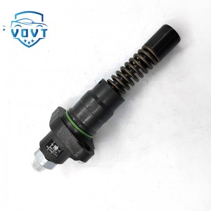
Diesel Fuel Injection Pump 0 445 010 019 Engine Auto Engine Part 0445010019


products description
| Reference Code | 0 445 010 019 |
| MOQ | 1 PCS |
| Certification | ISO9001 |
| Place of Origin | China |
| Packaging | Neutral packing |
| Quality Control | 100% tested before shipment |
| Lead time | 7~15 working days |
| Payment | T/T, Western Union, Money Gram, Paypal, Alipay, Wechat |
Multi-dimensional exploration and development prospects of oil pumps
I. Introduction
Oil pumps play an indispensable role in the operation of modern industrial systems and various types of mechanical equipment. From precise fuel delivery in automotive engine fuel systems to power transmission in industrial hydraulic systems, to efficient water delivery in agricultural irrigation, oil pumps ensure the stable operation of various systems by converting mechanical energy into fluid kinetic energy. Their performance directly impacts the efficiency, reliability, and energy efficiency of equipment. As equipment performance requirements continue to rise across various industries, oil pump technology continues to innovate and develop to meet increasingly diverse and demanding application requirements.
II. Working Principle Analysis
2.1 Positive Displacement Oil Pump Principle
Positive displacement oil pumps draw in and out liquid by periodically varying the volume of the pump chamber. For example, a common gear pump consists primarily of a pair of meshing gears and a pump body. When the driving gear rotates, it drives the driven gear in the opposite direction. On the side where the gears are disengaged, the pump chamber volume gradually increases, creating a partial vacuum. Liquid is drawn into the pump chamber under atmospheric pressure. On the side where the gears are engaged, the pump chamber volume decreases, squeezing the liquid and forcing it out of the pump. This operating mode enables positive displacement oil pumps to provide a relatively stable flow rate, making them particularly suitable for applications requiring high flow stability, such as the power source of hydraulic systems. Another example is a plunger pump, which relies on the reciprocating motion of a plunger within a cylinder to change the volume of the pump chamber. When the plunger moves outward, the pump chamber volume increases, drawing liquid in; when the plunger moves inward, the pump chamber volume decreases, expelling liquid. Plunger pumps can generate high pressures and are often used in high-pressure, low-flow applications, such as high-pressure liquid transportation in the petrochemical industry.
2.2 Vane Pump Principle
The operating principle of a vane pump is based on the sliding movement of vanes within rotor grooves and the action of centrifugal force. The pump primarily consists of a rotor, stator, vanes, and end caps. The rotor is eccentrically mounted within the stator. As the rotor rotates, the vanes slide against the inner surface of the stator under the influence of centrifugal force and oil pressure. With each rotation of the rotor, the vanes extend and retract within the rotor slots, causing the pump chamber volume to change periodically. During the outward extension phase, the pump chamber volume increases, drawing in liquid; during the inward retraction phase, the pump chamber volume decreases, discharging liquid. Vane-type oil pumps offer advantages such as compact structure, uniform flow rate, smooth operation, and low noise. They are widely used in equipment such as machine tool hydraulic systems and injection molding machines.
2.3 Centrifugal Pump Principle
Centrifugal pumps use the centrifugal force generated by the high-speed rotation of the impeller to transport liquid. The impeller is mounted within the pump casing and connected to the motor. When the motor drives the impeller at high speed, the centrifugal force propels the liquid within the impeller toward the outer edge of the impeller, increasing its velocity and pressure. The liquid then enters the pump casing. Within the pump casing, the liquid's velocity gradually decreases, and some of its kinetic energy is converted into pressure energy before being discharged through the pump's outlet. At the same time, a low-pressure area forms at the center of the impeller. Liquid is continuously drawn into the center of the impeller under the influence of external atmospheric pressure or liquid level differences. Centrifugal pumps feature high flow rates, a wide head range, simple structure, stable operation, and easy maintenance. They are widely used in agricultural irrigation, water supply and drainage systems, petrochemicals, and other fields. For example, in large-scale farmland irrigation projects, centrifugal pumps can transport large quantities of water from the water source to the fields, meeting the water needs of crop growth.
III. Common Types and Characteristics
3.1 Gear Pumps
Gear pumps have a simple structure, primarily consisting of gears, a pump body, end caps, and bearings. Their manufacturing process is relatively mature, resulting in low costs and easy maintenance. Because the gears engage and disengage continuously, gear pumps can provide continuous flow output. However, gear pumps have some inherent disadvantages, such as relatively small displacement and, under high-pressure conditions, high radial forces on the gears, which can lead to increased wear and shorten the pump's service life. Furthermore, during gear pump operation, the volume changes between the teeth during gear meshing can trap oil, causing pressure shock and noise. This, to a certain extent, limits their application in applications where noise and pressure stability are critical. However, gear pumps still find widespread application in areas where flow and pressure requirements are relatively low and cost-effectiveness is prioritized, such as small hydraulic systems and simple lubrication systems.
3.2 Plunger Pumps
Plunger pumps can be divided into axial and radial types based on the arrangement and movement of the plungers. In axial piston pumps, the plungers are arranged along the pump shaft, and the displacement is adjusted by changing the inclination angle of the swash plate or cylinder block. In radial piston pumps, the plungers are arranged radially on the rotor, and the rotation of the eccentric or cam causes the plungers to reciprocate. The outstanding advantage of plunger pumps is their ability to generate extremely high pressures, making them suitable for high-pressure, high-load applications, such as hydraulic systems in construction machinery and high-pressure water injection systems in oil production. Furthermore, plunger pumps have high volumetric efficiency, enabling them to maintain stable flow output at high pressures. However, plunger pumps are relatively complex in structure, require high manufacturing precision, and are expensive. Furthermore, due to the significant friction and wear between the plunger and the cylinder, lubrication and sealing requirements are extremely high, making maintenance difficult.
3.3 Vane Pumps
Vane pumps can be divided into single-acting and double-acting vane pumps. In a single-acting vane pump, the inner surface of the stator is circular, and the rotor is eccentric to the stator. The vanes slide within the rotor slots, completing both the oil suction and oil pressure process with each revolution. Variable flow can be achieved by varying the eccentricity. In a double-acting vane pump, the inner surface of the stator consists of two long-radius arcs, two short-radius arcs, and four transition curves. The rotor and stator are mounted concentrically, and the vanes complete both the oil suction and oil pressure process with each revolution, resulting in a relatively uniform output flow rate. Vane pumps offer advantages such as uniform flow rate, smooth operation, low noise, compact size, and light weight. They are suitable for precision hydraulic systems requiring high flow stability and low noise levels, such as machine tool feed systems and hydraulic servo systems. However, vane pumps require high oil cleanliness. Impurities in the oil can easily cause the vanes to stick, affecting the pump's proper operation.
3.4 Screw Pumps
Screw pumps primarily consist of a screw, a bushing, and a pump body. Based on the number of screws, they can be categorized as single-screw, twin-screw, and triple-screw pumps. A single-screw pump consists of a screw and a rubber bushing. The screw moves in a planetary motion within the bushing. The meshing and disengagement between the screw and bushing creates sealed chambers, through which the liquid is transported. Twin-screw and triple-screw pumps use intermeshing screws to propel the liquid from the intake to the discharge port. Screw pumps offer advantages such as continuous and uniform flow, low pulsation, smooth operation, low noise, and strong adaptability to liquids. They can transport high-viscosity liquids and those containing solid particles or fibers. They are widely used in liquid transportation in industries such as petroleum, chemical, and food. For example, in the crude oil transportation process after oil extraction, screw pumps can efficiently transport high-viscosity crude oil to gathering stations without causing blockages. However, their disadvantages are the high machining precision requirements for the screw and bushing, making repairs difficult and costly after wear.
IV. Performance Parameters and Their Significance
4.1 Flow Rate
Flow rate refers to the volume of liquid discharged by the pump per unit time, typically expressed as Q, with units such as cubic meters per second (m³/s) or liters per minute (L/min). Flow rate is a key indicator of a pump's operating capacity, determining how much liquid the pump can deliver per unit time. In practical applications, pumps with appropriate flow rates are selected based on different operating conditions. For example, in large industrial cooling systems, high-flow pumps are required to circulate the coolant to ensure adequate cooling. Meanwhile, lubrication systems for smaller equipment require relatively lower flow rates. The flow rate of an oil pump is not fixed; it is affected by factors such as the pump's speed, structural parameters, and operating pressure. Generally speaking, within a certain range, higher pump speeds increase flow rates, and larger pump dimensions also increase flow rates. However, when operating pressure increases, the actual flow rate may decrease due to factors such as pump leakage.
4.2 Head (Pressure)
Head refers to the energy gain per unit weight of liquid passing through the pump. For centrifugal pumps, head (measured in meters of liquid column, m) is often expressed, while for positive displacement pumps, pressure (measured in megapascals, MPa) is often used. Head (pressure) reflects the pump's ability to overcome pipeline resistance, lift liquid height, and meet system process requirements. In practical engineering, the required pump head (pressure) is determined based on factors such as the distance and height of the liquid to be transported, as well as the resistance of the pipeline system. For example, in a high-rise building's water supply system, the pump must provide sufficient head to ensure smooth water delivery to all floors. In a hydraulic system, the pump must output a corresponding pressure to drive actuators to perform various operations. Insufficient pump head (pressure) will result in improper liquid delivery or system malfunction. Excessive head (pressure) will waste energy and may even damage equipment. 4.3 Efficiency
Oil pump efficiency refers to the ratio of the pump's output power to its input power. It reflects how effectively the pump converts mechanical energy into liquid energy. Higher efficiency indicates less energy loss during operation and more efficient energy utilization. Oil pump efficiency primarily includes volumetric efficiency, mechanical efficiency, and hydraulic efficiency (for centrifugal pumps, etc.). Volumetric efficiency refers to the ratio of the pump's actual output flow rate to its theoretical flow rate. It is primarily affected by internal pump leakage; greater leakage indicates lower volumetric efficiency. Mechanical efficiency refers to the ratio of the power consumed to overcome mechanical friction within the pump to the input power. Mechanical efficiency is also affected by factors such as the machining accuracy of mechanical components and lubrication conditions. Hydraulic efficiency (for centrifugal pumps, etc.) refers to the ratio of the actual energy gained by the liquid flowing through the pump to the theoretical energy gained. It is dependent on factors such as the pump's flow path design and the liquid's flow conditions. Improving oil pump efficiency is crucial for energy conservation, emission reduction, and lowering operating costs. In practical applications, oil pump efficiency can be improved by optimizing the pump's structural design, selecting appropriate materials, improving machining accuracy, and improving lubrication conditions. 4.4 Speed
Speed refers to the number of revolutions per minute (RPM) of the oil pump shaft, typically expressed as n, measured in revolutions per minute (r/min). Speed significantly impacts performance parameters such as oil pump flow rate, head (pressure), and efficiency. Generally, within a certain range, increasing speed increases the flow rate and head (pressure) of the oil pump. However, excessively high speeds can also lead to problems such as increased wear of pump components, increased noise, and increased cavitation. They can also exceed the motor's rated power, leading to motor overload. Therefore, when selecting an oil pump speed, it's important to consider factors such as pump performance requirements, operational reliability, and motor compatibility. Different oil pump types have different suitable speed ranges. For example, gear pumps are generally suitable for low to medium speeds, while centrifugal pumps perform better at higher speeds.
Products categories
-

Diesel Fuel Injection Pump P5594766 V81CF304 E...
-
Fuel Injector Unit Pump 0414693005 for Deutz En...
-

High Quality Fuel Injector Pump 9521A320T For P...
-

Diesel Fuel Injection Pump DB4429-6090 Engine A...
-

Super Quality Diesel Fuel Injection Pump CW0940...
-

Diesel Fuel Injection Pump 729932-51400 Engine ...


