
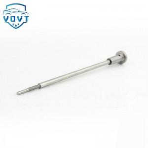
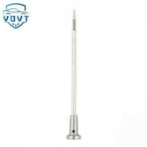
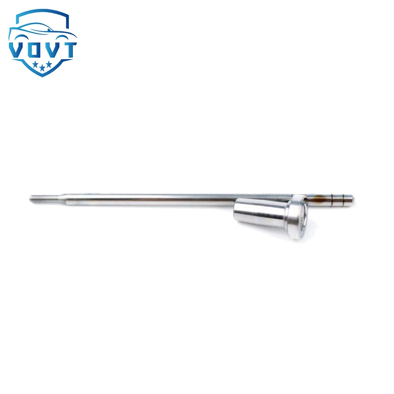
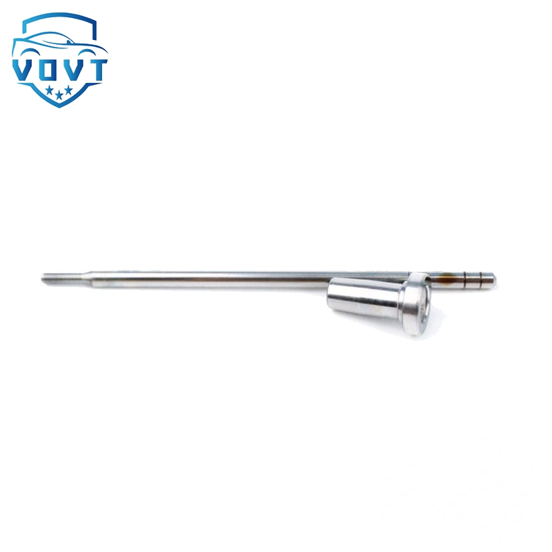
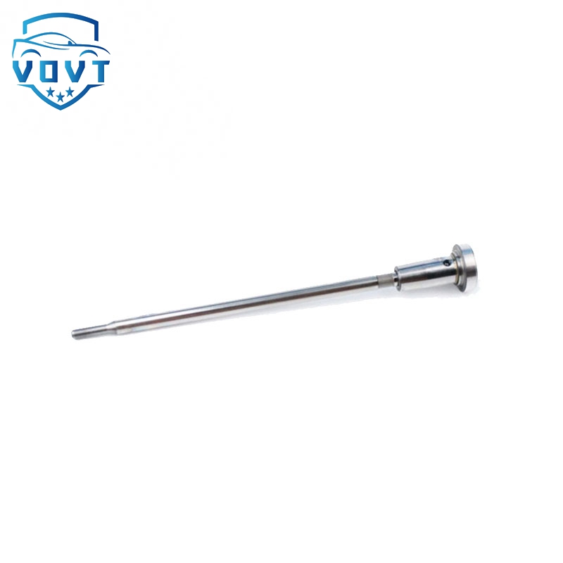
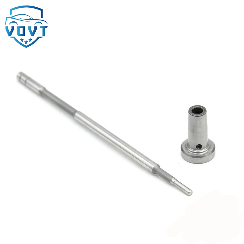
Common Rail Fuel Injector Control Valve Assembly F00RJ01052 for Injector 0445120028 0445120069


products detail
Used in Vehicles / Engines
| Product Code | F00RJ01052 |
| Engine Model | / |
| Application | 0445120028 0445120069 |
| MOQ | 6 pcs / Negotiated |
| Packaging | White Box Packaging or Customer's Requirement |
| Warranty | 6 months |
| Lead time | 7-15 working days after confirm order |
| Payment | T/T, PAYPAL, as your preference |
Transient states analysis of CI engine injectors with the use of optical methods (PART 5)
The investigations were conducted for values of parameters typical for normal operation of internal combustion engine. The research plan was created with the aim to determine the influence of each parameter on the injection delay time. As the variables of the process were chosen: the injection pressure, the back-pressure and the injection duration. It should be noticed that the last parameter has to get higher value for solenoid injector because of lower fuel flow rate. The range of parameters variation is shown in table 2.
2.1. Electrical signal analysis During the tests, the electric parameters were recorded (figure 2). This data was used to determine the time delay between the starting impulse and the proper electrical signal (measured in the injector with the use of AVL Concerto software). The starting impulse was selected as the start of TTL control signal for the injector; the finish point of this analysis was set as the time when the response on current clamps was observed. The difference between those two points was signed as t-e and describes the hardware delay in the injection system. In this analysis the time t-d was defined as the time from the start of the impulse (for injector) to the diode response. The meaning of this time will be explained further in this chapter.
3.4. Analysis of optical tests Pictures from optical tests were analysed with the usage of DaVis software from LaVision. The methodology of picture analysis is explained in figure 3. The recording speed was set on 250 kfps with the spatial resolution of 128 × 16 pixels. At the beginning, the background was subtracted from the raw images to achieve a clear picture of the fuel spray development. The first picture analysed to determine the injection delay was the picture with a diode visible on left side (third photo in figure 3). The diode flash time was set at the value of 4 µs, so it was possible to observe the diode on one frame only. The next step of the analysis was to find the frame where the pixels near the injector nozzle changed their illumination level. The change in illumination means occurrence of fuel drops. That time was described as t-o.
Products categories
-

Common Rail Fuel Injector Control Valve Assembl...
-

Auto parts Diesel Fuel Injector Control Valve F...
-

Auto parts Diesel Fuel Injector Control Valve F...
-
Common Rail Control Valve Assembly F00RJ01522 f...
-

Auto parts Diesel Fuel Injector Control Valve F...
-

High Quality New Common Rail Diesel Injector Co...


