
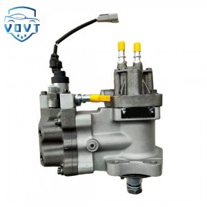
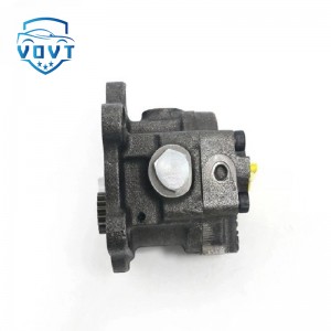
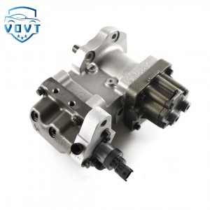
3975375 Fuel Injection Pump fits for Cummins QSL9 Engine Parts


products description
| Reference Code | 3975375 |
| MOQ | 1PCS |
| Certification | ISO9001 |
| Place of Origin | China |
| Packaging | Neutral packing |
| Quality Control | 100% tested before shipment |
| Lead time | 7~10 working days |
| Payment | T/T, L/C, Paypal, Western Union, MoneyGram or as your requirement |
Fuel pump control circuit principle
There are three types of fuel pump control circuits: ECU-controlled fuel pump control circuit, switch-controlled fuel pump control circuit, and fuel pump control circuit with speed control.
1.ECU controlled oil pump control circuit
(1) When the ignition switch is turned on, current flows through the main relay coil, the contacts are closed, and the power supply supplies power to the EFI.
(2) When the engine is started, the starting device (ST) terminal of the ignition switch is connected, and the coil L2 in the circuit breaker relay is energized, which generates suction to close the contacts of the circuit breaker relay. The power supply is supplied to the fuel pump, and the fuel pump is put into operation.
(3) Once the engine is started, the speed sensor will input the engine speed signal Ne into the ECU. At this time, the transistor VT in the ECU is turned on, and the coil L1 in the circuit breaker relay is energized, so that its contacts continue to remain closed, and the fuel pump continues to work.
(4) When the engine stops working, the VT is disconnected, the circuit breaker relay contacts are disconnected, the power supply line of the fuel pump is interrupted, and the fuel pump stops working.
2. Switch-controlled fuel pump control circuit
(1) Turn on the ignition switch, the main relay contacts are closed, and the power supply supplies power to the EFI system.
(2) When starting, the ignition switch is connected to the ST terminal, the circuit breaker relay coil L2 is energized, the circuit breaker relay contacts are closed, and the fuel pump starts to work.
(3) The engine is running, and the air sucked into the engine flows through the air flow meter. The measuring plate in the air flow meter rotates, turning on the fuel pump switch, and the coil L1 of the circuit breaker relay starts to be energized.
3. Fuel pump control circuit with speed control
(1) When the engine is working at low speed or medium to small load, the transistor in the ECU is turned on, and the coil of the fuel pump control relay is energized, causing contact B to close. Because of the resistor placed in series with the circuit, the oil pump operates at a low speed.
(2) When the engine is running at high speed and heavy load, the transistor in the ECU is cut off and contact A is closed. The fuel pump is directly connected to the power supply and runs at high speed.
Products categories
-
Fuel Pump 292-3751 2923751 for CAT Engine CAT S...
-

Diesel Fuel Injection Pump 0 445 020 023 044502...
-

High Efficiency Diesel Pump 0K65A-13800K Fuel I...
-

China-Made New Diesel Fuel Electronic Unit Pump...
-
High Quality Diesel injector Pump CCR1600 49542...
-

High Pressure Diesel Fuel Injection Pump 0 460 ...


