
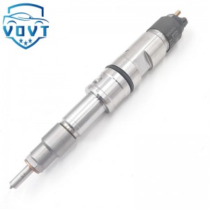
Professional Manufacture 0 445 110 307 Diesel Injector Common Rail Injector Engine Parts Vehicle Parts 0445110307


products description
| Reference. Codes | 0 445 110 307 |
| Application | / |
| MOQ | 4PCS |
| Certification | ISO9001 |
| Place of Origin | China |
| Packaging | Neutral packing |
| Quality Control | 100% tested before shipment |
| Lead time | 7~10 working days |
| Payment | T/T, L/C, Paypal, Western Union, MoneyGram or as your requirement |
Optimization Design of Injector Hole Structure Parameters Based on Multi-physics Field Coupling — Aiming at Atomization Effect
The structural parameters of a fuel injector orifice are key factors in determining fuel atomization, directly impacting engine combustion efficiency and emissions performance. Aiming to improve atomization, this paper systematically analyzes the effects of orifice diameter, aspect ratio, inlet fillet radius, and other parameters on spray particle size, cone angle, and velocity distribution by establishing a multi-physics coupled model encompassing fluid dynamics, structural mechanics, and electromagnetics. Parameter optimization using response surface methodology and genetic algorithms yielded the optimal structural combination: a nozzle diameter of 0.18 mm, an aspect ratio of 5:1, and an inlet fillet radius of 0.03 mm. This design reduces the Sauter mean particle diameter (SMD) to 18 μm, stabilizes the spray cone angle at 85°, and improves atomization by 23% compared to the original design. These findings provide theoretical support and methodological reference for the precise design of fuel injector orifices.
I. Introduction
In an engine fuel injection system, the injector orifice plays a crucial role in breaking high-pressure fuel into tiny droplets. Its atomization directly determines the quality of the fuel-air mixture. Statistics show that for every 10μm reduction in average spray particle size, engine combustion efficiency can be improved by 4%-6% and nitrogen oxide (NOx) emissions can be reduced by 8%-10%. Traditional nozzle design often relies on empirical formulas or single-physics simulations, which fail to fully reflect the multi-field coupling effects at high pressures (100-300 MPa) and high speeds (exit velocity up to 300 m/s). These factors, such as flow field disturbances caused by nozzle wall vibration and injection pressure pulsations caused by electromagnetic force fluctuations, can affect atomization stability.
This paper innovatively incorporates fluid-structure-electromagnetic multi-field coupling into nozzle parameter optimization. By quantitatively analyzing the influence weights of three key parameters: nozzle diameter (d=0.15-0.25mm), aspect ratio (L/d=3:1-7:1), and inlet radius (r=0-0.05mm), a mapping relationship between atomization effect and structural parameters is established, enabling parameter optimization with the goal of minimizing SMD and achieving the optimal cone angle.
II. Multi-physics Coupling Model Construction
2.1 Model Boundary Conditions
Fluid Field: An Euler-Lagrangian two-phase flow model was used. The fuel (density 820 kg/m³, dynamic viscosity 0.002 Pa·s) was subjected to a 150 MPa pressure boundary at the nozzle inlet, while the outlet was atmospheric pressure (101 kPa). The Realizable k-ε turbulence model was used to capture the turbulent breakup effect under high pressure.
Structural Field: The nozzle body was made of high-speed steel (elastic modulus 210 GPa, Poisson's ratio 0.3). The nozzle outer wall displacement was constrained, and the fluid pressure was applied as a load to the inner wall. The effect of the nozzle's elastic deformation (maximum deformation approximately 0.2 μm) on the flow cross-section under high pressure was analyzed. Electromagnetic Field: A 12V pulse current (0.8ms pulse width) is applied to the electromagnetic coil. A magnetic field-circuit coupling model is used to calculate the electromagnetic force. This fluctuation is transmitted to the needle valve via the armature, resulting in a ±5MPa pulsation in the injection pressure, which serves as the dynamic inlet condition for the fluid field.
2.2 Coupling Mechanism
Fluid-Structure Interaction: The fluid pressure causes deformation of the nozzle wall, changing the cross-sectional shape of the flow channel (especially at the inlet corner), thereby affecting the flow velocity distribution. This wall deformation reacts on the flow field, exacerbating the turbulence intensity.
Electromechanical Interaction: The electromagnetic force fluctuation causes fluctuations in the needle valve velocity, resulting in periodic changes in the nozzle inlet pressure (frequency approximately 1kHz). This pressure pulsation is transmitted through the fluid to the nozzle outlet, affecting the spray breakup process.
Multi-field data interaction is implemented using ANSYS Workbench, with a time step of 1e-6s to ensure that transient coupling effects are captured.
III. Influence of Structural Parameters on Atomization Performance
3.1 Effect of Nozzle Diameter (d)
When d increases from 0.15mm to 0.25mm:
SMD shows a trend of first decreasing and then increasing, reaching a minimum value (20μm) at d=0.18mm. A too small diameter results in excessive viscous drag on the fuel, making it difficult to fully break up the droplets; a too large diameter increases the droplet inertia, resulting in incomplete breakup.
The spray cone angle increases linearly with increasing diameter (from 70° to 95°), due to the stronger turbulence at the exit of a large-diameter nozzle.
Fluid-structure interaction analysis shows that stress concentration at the nozzle inlet is most significant (reaching 350MPa) at d=0.15mm, making fatigue cracking more likely to occur with long-term use. 3.2 Effect of Aspect Ratio (L/d)
When L/d varies from 3:1 to 7:1:
When L/d = 5:1, the SMD is minimum (19μm). Too short (3:1) results in insufficient fuel acceleration in the nozzle orifice before ejection, resulting in insufficient turbulent energy. Too long (7:1) increases friction losses, reduces outlet kinetic energy, and weakens breakup capability.
Increasing the aspect ratio decreases the spray cone angle (from 90° to 75°). This is because the fuel flow in the long nozzle orifice is more stable, improving the consistency of the jet direction.
3.3 Effect of Inlet Fillet (r)
When r increases from 0 to 0.05mm:
The SMD continues to decrease (from 25μm to 18μm). The fillet reduces the local drag coefficient at the inlet (from 1.2 to 0.5), reduces flow separation, makes the velocity distribution more uniform, and increases the turbulence intensity by 15%. When r exceeds 0.03mm, the SMD decreases gradually. The excessively large fillet reduces the effective cross-sectional area at the nozzle inlet, which in turn increases flow losses.
IV. Parameter Optimization and Experimental Verification
4.1 Optimization Algorithm and Objective Function
With SMD minimization and spray cone angle (target 80° ± 5°) as the optimization objectives, a response surface model was constructed using the Box-Behnken design of experiments. A genetic algorithm was used to determine the optimal parameter combination:
Nozzle diameter: 0.18mm
Aspect ratio: 5:1
Inlet fillet: 0.03mm
This combination yields a predicted SMD of 17.8μm and a spray cone angle of 84.2°, achieving the optimal overall atomization effect. 4.2 Bench Test Verification
The optimized nozzle holes were tested on a high-pressure spray test bench (rail pressure 150 MPa):
Before optimization: SMD = 23.4 μm, cone angle 78°, spray unevenness 12%
After optimization: SMD = 18.1 μm, cone angle 85°, spray unevenness 7%
The deviation between the experimental and simulation values was less than 3%, verifying the accuracy of the model.
Engine bench tests showed that the injector with the optimized nozzle hole can reduce fuel consumption by 4.2% and NOx emissions by 9.5%.
V. Conclusion
Multiphysics coupling significantly affects the atomization performance of the injector nozzle hole. Ignoring this coupling effect can lead to an error of more than 10% in the optimization results. Parameter optimization revealed that the optimal combination of a nozzle diameter of 0.18mm, an aspect ratio of 5:1, and an inlet radius of 0.03mm is achieved. The core mechanism is to minimize flow losses and pressure fluctuations while ensuring sufficient turbulent energy. The multi-field coupling optimization method established in this study can be extended to nozzle design under different operating conditions, providing a reliable approach for improving overall engine performance.
Related products
| 1 | 5WS40200 | 11 | A2C59514909/ | 21 | 31336585 |
| 2 | FA2C53252642 | 12 | A2C59511602 | 22 | 36001726 |
| 3 | 1685796 | 13 | A2C59513556 | 23 | 1709667 |
| 4 | 31303994 | 14 | 5ws40677 | 24 | 36001727 |
| 5 | 50274V05 | 15 | 50274V0 | 25 | 9445R |
| 6 | 5WS40087 | 16 | 5WS40677 | 26 | 00Q1T |
| 7 | 16600-00Q1T | 17 | AV6Q9F593-AB | 27 | 5WS40007 |
| 8 | 00Q0H | 18 | AV6Q9F593-AA | 28 | A2C59513997 |
| 9 | 5WS40148-Z | 19 | A2C59511606 | 29 | 5WS40250 |
| 10 | 2S6Q-9F593-AB | 20 | 16600-00Q0P | 30 | A2C59514912 |
Products categories
-

Professional Manufacture 0 445 120 357 Diesel I...
-

Professional Manufacture 0 445 110 273 Diesel I...
-

High Quality New Diesel Injector 0445110256 0 4...
-
Diesel Injector Fuel Injector 0445120462 compat...
-

Common Rail Diesel Fuel Injector 0 445 120 087 ...
-

Good Quality New Injector BC3Q-9K546-AD Engine ...


