
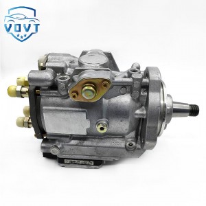
New Original Pressure Regulator Suction Pressure Valve Control Valve 0 928 400 617 0928400617 for Auto Spare Parts


Products Description
| Reference Codes | 0 928 400 617 |
| Application | / |
| MOQ | 12PCS |
| Certification | ISO9001 |
| Place of Origin | China |
| Packaging | Neutral packing |
| Quality Control | 100% tested before shipment |
| Lead time | 7~10 working days |
| Payment | T/T, L/C, Paypal, Western Union, MoneyGram or as your requirement |
In-depth analysis of the control valve structure
I. Introduction
In industrial automation systems, control valves are core devices for precise fluid control. Their structural composition determines the valve's flow control accuracy, flow capacity, sealing performance, and adaptability to diverse operating conditions. A thorough understanding of control valve structure is crucial for improving the stability, efficiency, and safety of industrial production processes.
II. Valve Body Assembly Structure Analysis
2.1 Valve Body Structure
As the fluid flow channel, the valve body's shape, material, and internal flow path design have a profound impact on valve performance. Common valve body shapes include straight-through, angle, and three-way. Straight-through valve bodies offer a straight flow path, ensuring smooth media flow and minimal flow resistance, making them widely used in most fluid control scenarios, such as general pipeline transportation systems. Angle valve bodies are suitable for applications requiring fluid flow direction change, such as in the inlet and outlet connections of heat exchangers, facilitating fluid diversion and reducing the complexity of piping layouts. Three-way valve bodies can split one fluid path into two, or combine two fluid paths into one, and are commonly used in processes requiring fluid distribution or mixing, such as material proportioning in chemical production. The valve body material is selected based on the characteristics of the working medium and operating conditions. For normal temperature and low-pressure environments with media such as water and air, cast iron is widely used due to its low cost and excellent machinability. For high-temperature, high-pressure, and corrosive media, such as acidic gases or high-temperature steam in the petrochemical industry, corrosion-resistant, high-strength materials such as stainless steel and alloy steel are preferred to ensure long-term stable operation of the valve body and prevent failures such as leakage caused by corrosion or pressure.
Internal flow path design is critical to valve body construction. Ideally, the flow path should be as smooth as possible to minimize turbulence and pressure loss during fluid flow. Some advanced valve bodies feature streamlined designs. Using computer-generated fluid dynamics (CFD) technology, the flow path geometry is optimized to ensure smoother fluid flow within the valve body, effectively reducing energy loss and improving valve flow capacity. For example, the flow path design of some high-performance control valves can increase flow capacity by 10%-20% for the same diameter.
2.2 Valve Plug and Seat Structure
The valve plug and seat are the core components of a control valve that perform flow regulation and sealing functions. Valve cores come in a variety of shapes, with common ones including plunger, window, and sleeve types. Plunger-type valve cores have a simple structure and achieve a good seal through close contact with the valve seat. They are suitable for applications with strict leakage requirements, such as fluid control in the pharmaceutical and food processing industries, where leakage can be kept to extremely low levels. Window-type valve cores adjust flow by varying the opening of a window, offering greater flow capacity and suitable for high-flow applications with relatively low requirements for regulation accuracy, such as flow control in some industrial cooling systems. Sleeve-type valve cores feature a unique cage structure that effectively guides fluid flow, reducing cavitation and noise. They are suitable for complex applications with high pressure differentials and high flow rates, such as high-pressure water injection systems in oil production.
The valve seat and valve core fit tightly together, and their sealing performance directly affects the valve's leakage. Sealing methods primarily include metal hard seals and soft seals. Metal hard seals utilize wear-resistant materials such as carbide and are suitable for applications with high temperatures, high pressures, and media with a certain particle size. They can withstand high pressure and erosion, but their sealing accuracy is relatively low, and leakage is generally within a certain range. Soft seals are often made of polymer materials such as polytetrafluoroethylene (PTFE), offering excellent sealing performance and near-zero leakage. They are often used in low-temperature, low-pressure applications where leakage requirements are extremely high, such as high-purity gas transportation in the electronics industry. To improve sealing performance, some high-end control valves employ a combination of metal and soft materials, leveraging the advantages of each sealing method.
2.3 Valve Stem and Guide Structure
The valve stem connects the valve core to the actuator, transmitting the actuator's driving force and enabling precise movement of the valve core within the valve seat. The valve stem must possess sufficient strength and rigidity to withstand the actuator's thrust or pull while ensuring accurate and stable valve core movement. For high differential pressure and large-diameter valves, valve stem strength requirements are even higher. High-strength alloy steel is often used, and specialized heat treatment processes are performed to enhance its yield strength and fatigue life.
Guide structures guide the movement of the valve stem, ensuring accurate centering between the valve core and the valve seat. Common guide structures include bonnet guides and sleeve guides. The bonnet guide structure is simple, using a guide sleeve installed on the bonnet to guide the valve stem. It is suitable for small and medium-sized valves. The sleeve guide structure uses a sleeve installed within the valve body, within which the valve stem moves. This structure offers high guiding precision and effectively reduces valve core vibration and wear. It is suitable for high-pressure, large-diameter valves with high control accuracy requirements, such as steam control valves in the power industry.
III. Actuator Assembly Structure Analysis
3.1 Pneumatic Actuator
Pneumatic actuators, powered by compressed air, offer significant advantages such as simple structure, rapid actuation, and safety and explosion-proofing. They are widely used in industry. The main types are diaphragm and piston types.
A diaphragm pneumatic actuator consists of a diaphragm, a spring, and a push rod. When compressed air enters the diaphragm chamber, the diaphragm deforms under pressure, overcoming the spring force to push the push rod, which in turn drives the valve stem and valve core. The compact multi-spring diaphragm actuator features a compact structure, small dimensions, and light weight. Compared to traditional single-spring structures, its overall height can be reduced by approximately half, its weight by 30%-40%, and its actuation is more sensitive, with response time shortened by 10%-20%, offering significant advantages in installations with limited space.
Piston-type pneumatic actuators offer high output force and are suitable for high-pressure differentials and large-diameter valves. Their piston can move in both directions within the cylinder, with the air source pressure controlling the piston's direction of movement, thereby opening and closing the valve core. Compared to diaphragm actuators, piston-type actuators can withstand higher air source pressures, typically around 0.5 MPa, compared to 0.25 MPa for diaphragm actuators. Therefore, piston-type actuators provide more stable and powerful driving force under high-pressure conditions.
3.2 Electric Actuators
Electric actuators convert electrical energy into mechanical energy, using a motor to drive a reduction gear, thereby moving the valve stem. They offer high control accuracy, fast response speed, and remote control capabilities, making them suitable for applications requiring extremely high control precision and automation, such as semiconductor manufacturing and precision chemicals.
Electric actuators utilize a variety of motor types, with servo motors and stepper motors being common. Servomotors offer excellent speed regulation and torque control capabilities, precisely adjusting output speed and torque based on control signals to achieve precise valve spool positioning with positioning accuracy within ±0.1%. Stepper motors control the motor's rotation angle using pulse signals, offering high positioning accuracy and reliability, making them suitable for applications requiring precise control of valve opening. Electric actuators also incorporate components such as a controller and an encoder. The controller receives control signals and controls the motor, while the encoder provides real-time feedback on the motor's position and speed, forming a closed-loop control system that further improves control accuracy and stability.
3.3 Hydraulic Actuators
Hydraulic actuators use liquid (such as hydraulic oil) as their motive medium and offer advantages such as high output force, fast response, and smooth operation. They are suitable for large, high-pressure valves requiring high control precision, such as large blast furnace gas regulating valves in the metallurgical industry. Hydraulic actuators primarily consist of a hydraulic cylinder, a hydraulic pump, a control valve block, and a fuel tank. The hydraulic pump pressurizes the hydraulic oil in the tank and delivers it to the hydraulic cylinder, moving the piston and, in turn, the valve stem and spool. The control valve block precisely adjusts the flow and pressure of the hydraulic oil, enabling precise control of the actuator's output force and speed. The output force of hydraulic actuators can be tailored to specific needs, meeting the high thrust requirements of specialized operating conditions. Their output force can be several times greater than that of pneumatic actuators of the same specification. Furthermore, due to the incompressibility of liquid, hydraulic actuators operate more smoothly and have strong anti-interference capabilities, effectively preventing valve malfunctions caused by external interference.
IV. Conclusion
The control valve structure is complex and sophisticated. The valve body assembly and actuator assembly work together to determine the performance of the control valve. The valve body structure, valve core and valve seat design, and valve stem guide structure affect the valve's flow capacity, sealing performance, and adjustment accuracy. Different types of actuators, such as pneumatic, electric, and hydraulic, give the control valve its driving ability and control characteristics under different operating conditions. In actual applications, it is necessary to comprehensively consider various structural factors based on specific process requirements, media characteristics, and operating conditions, rationally select the control valve type, and continuously optimize its structural design to achieve precise and efficient control of fluids in industrial production processes and promote the continuous improvement of industrial automation levels.
Products categories
-
High-Quality Diesel Fuel Injection Pump 09342-4...
-

New Original Pressure Regulator Suction Pressur...
-

High Quality Diesel Head Rotor 146403-4920 VE P...
-

Made in China Fuel Injection Pump Plunger A724 ...
-

High Efficiency VE Pump Rotor Head 146403-9720 ...
-

Diesel Fuel Injection Pump PES6A95D320RS2000 En...


