
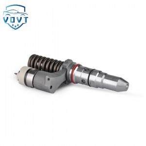
New High Quality Diesel Injector 4W7017 4W7018 4W7019 8N7005 7W7026 7W7045 170-5181 For CAT


Products Description
| Reference. Codes | 8N7005 |
| Application | 8N7005 |
| MOQ | 4PCS |
| Certification | ISO9001 |
| Place of Origin | China |
| Packaging | Neutral packing |
| Quality Control | 100% tested before shipment |
| Lead time | 7~10 working days |
| Payment | T/T, L/C, Paypal, Western Union, MoneyGram or as your requirement |
The structure of the injector
Basic structure of electromagnetic drive injector
1. Main body shell and fuel interface
Metal shell:
Function: protect internal precision parts and provide installation fixing points (such as fixed on the intake manifold or cylinder head through a sealing ring).
Fuel interface:
Fuel inlet: connect to the fuel pipeline and receive high-pressure fuel from the fuel pump.
Internal oil circuit: fuel flows to the nozzle through the channel in the shell.
2. Electromagnetic drive assembly
Electromagnetic coil:
Location: located in the middle of the injector, wound on the skeleton.
Function: generate magnetic field after power is turned on, attracting the armature (or needle valve) to move.
Armature and spring:
Armature:
Rigidly connected to the upper end of the needle valve, it drives the needle valve to move when subjected to electromagnetic force.
Reset spring:
Location: located above the armature and fixed by the spring seat.
Function: push the armature and needle valve to reset through elastic force when the power is off, and close the injection hole.
Magnetic isolation sleeve:
Material: material with poor magnetic conductivity (such as stainless steel).
Function: Isolate the magnetic field of the electromagnetic coil to avoid magnetic force dispersion and concentrate on the armature.
3. Injector assembly
Needle valve and valve seat:
Needle valve:
The lower end is conical or ball valve structure, and it is precisely matched with the valve seat (the gap is only a few microns).
When opened, the fuel is sprayed out through the gap between the needle valve and the valve seat.
Valve seat:
Located at the bottom of the injector, the surface is hardened (such as carbide plating), and it is resistant to high-pressure fuel erosion.
Nozzle body (spray hole):
Structure:
Single-hole nozzle: used in early models, the spray is conical, and the atomization depends on the intake airflow.
Multi-hole nozzle (common 2-12 holes):
The number and angle of holes are optimized according to the combustion chamber design. For example, the direct injection injector in the cylinder often uses 6-8 holes, and the spray is fan-shaped or conical, covering the spark plug or a specific area of the combustion chamber.
Aperture: Usually 0.1-0.3mm, the smaller the aperture, the finer the atomization, but it is easy to clog.
Filter:
Location: at the nozzle entrance (or near the fuel inlet).
Function: filter impurities (such as metal particles, colloid) in the fuel to prevent clogging of the spray hole.
4. Electrical connection components
Wire harness plug:
Pin: usually 2 pins (positive power supply, ECU control signal).
Function: receive the pulse signal of the ECU and control the on and off of the electromagnetic coil.
Sealing ring:
Location: between the injector and the mounting seat (such as the intake manifold).
Material: high temperature resistant rubber (such as fluororubber).
Function: prevent fuel leakage and external air infiltration, and buffer vibration.
Structural differences between different types of injectors
1. Direct injection injector vs. manifold injection injector
Project Direct injection injector Manifold injection injector
Working pressure Up to 100-200bar (need to withstand high pressure in the combustion chamber) 3-5bar (need to overcome only negative pressure in the intake manifold)
Nozzle structure Multi-hole fine pores (smaller pore size, such as less than 0.1mm), more precise spray angle Single hole or multiple holes (larger pore size), relying on intake air flow atomization
Drive mode Mostly electromagnetic drive or piezoelectric drive Electromagnetic drive
Installation position Directly inserted into the cylinder head and extended into the combustion chamber Installed on the intake manifold, aligned with the intake valve
2. Piezoelectric injector (high-end models)
Core difference:
Replace electromagnetic coil with piezoelectric ceramic elements.
Principle: After power is turned on, the piezoelectric ceramic expands rapidly (response time is nanoseconds), pushing the needle valve to open, and the ceramic shrinks and resets after power is turned off.
Advantages:
Faster response speed (more than 30% faster than electromagnetic type), suitable for high-frequency injection (such as direct injection stratified combustion).
Higher control accuracy, multiple injections (such as pre-injection, main injection, post-injection) can be achieved.
Technical requirements for key components
Sealing:
The needle valve and valve seat must be polished to mirror accuracy to ensure no fuel leakage under high pressure (such as the leakage of the direct injection injector under 200bar pressure must be <5ml/min).
Corrosion resistance:
Parts in contact with fuel (such as nozzles, needle valves) must be made of stainless steel, hard alloy or nickel-phosphorus alloy to resist sulfide corrosion in the fuel.
Fatigue resistance:
The electromagnetic coil must be resistant to high temperatures (the engine compartment temperature can reach more than 100℃), and the spring must withstand more than one million compressions without deformation.
Products categories
-

Top Quality Fuel injector Assembly Diesel Commo...
-

New High Quality Diesel Injector 374-0751 30R-0...
-

New High Quality Diesel Injector 229-5918 10R-1...
-

New High Quality Diesel Injector 211-3023 10R-8...
-
New High Quality Diesel Injector 292-3666 20R-8...
-
Auto Parts Fuel Injector Diesel Injection 249-0...


