
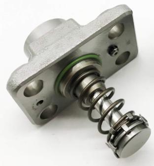
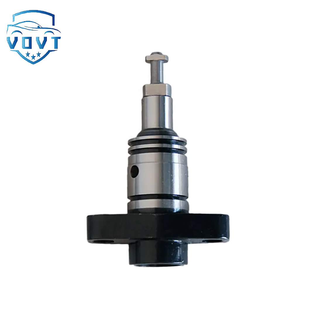
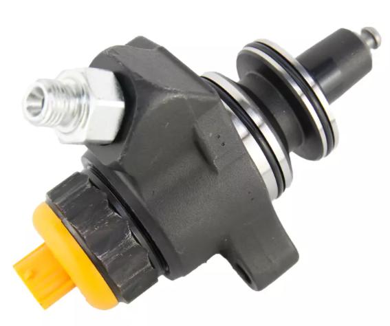
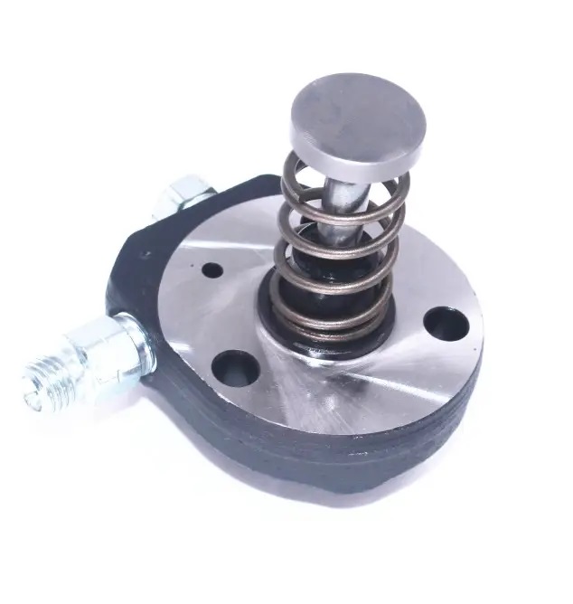
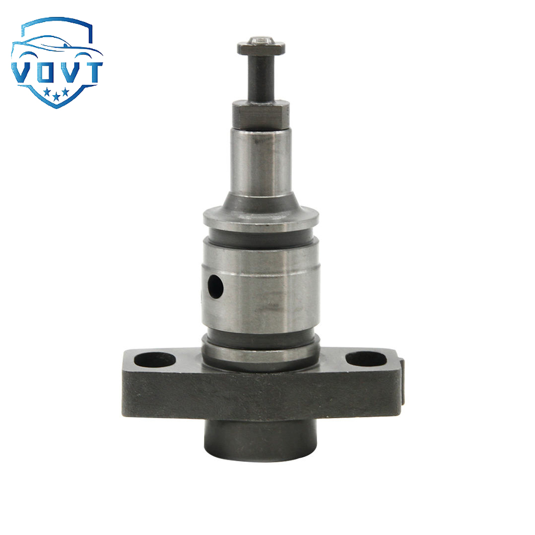
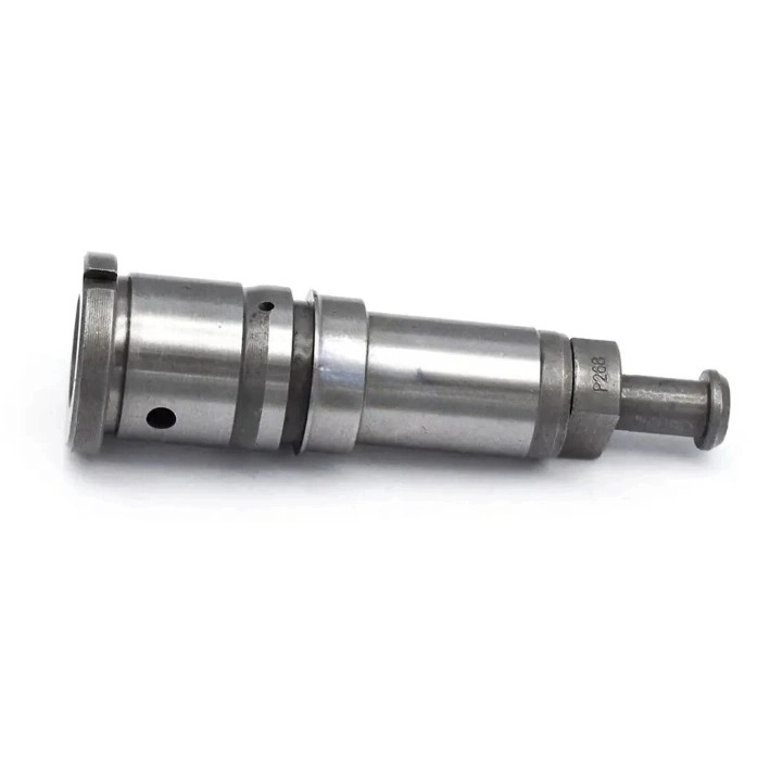
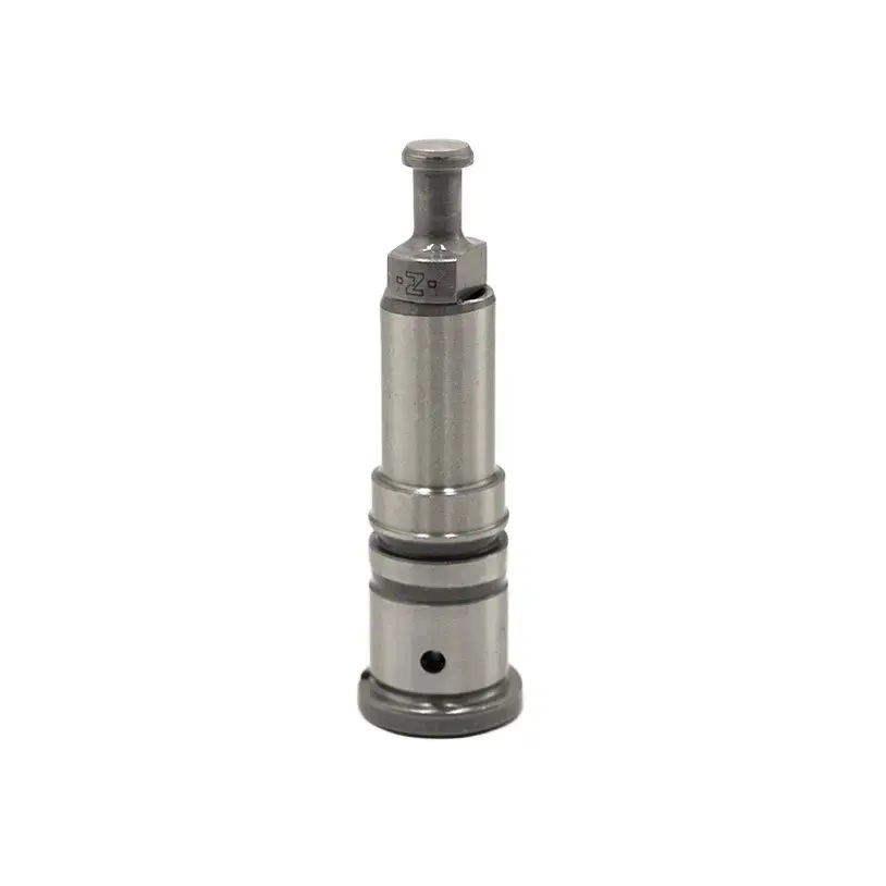
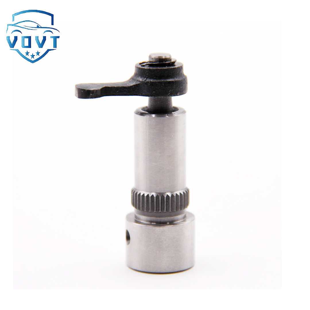
Made in China Fuel Injection Pump Plunger S1100 8mm Pump Elements Engine Accessories


products description
| Reference. Codes | S1100 |
| OE/OEM Codes | / |
| Application | / |
| MOQ | 5 PCS |
| Certification | ISO9001 |
| Place of Origin | China |
| Packaging | Neutral packing |
| Quality Control | 100% tested before shipment |
| Lead time | 7~15 working days |
| Payment | T/T, Paypal, Western Union or as your requirement |
Introduction of oil pump plunger
Comprehensive introduction of oil pump plunger: structure, principle and application
1. Definition and core function of oil pump plunger
The oil pump plunger is a key moving part in the fuel pump or hydraulic pump, which realizes the suction and pressurized delivery of fluid (fuel, hydraulic oil, etc.) through reciprocating linear motion. Its core functions are:
Pressure generation: In the diesel engine injection pump, the plunger compresses the fuel through high pressure (up to 2000 bar or more) to meet the atomization requirements of the injector;
Flow control: By adjusting the effective stroke or working frequency of the plunger, the output flow is accurately controlled (such as oil volume adjustment in the common rail system);
Sealed transmission: It forms a precision pair with the plunger sleeve to prevent leakage of high-pressure fluid and ensure system efficiency.
2. Structural composition and working principle
1. Typical structural components
Plunger body: a cylindrical metal part with a hemispherical or flat top and a transmission mechanism (such as a camshaft drive) connected to the bottom;
Plunger sleeve: a precision sleeve that matches the plunger, with the inner wall ground and polished, and a matching clearance of only 5-10μm, forming a "plunger pair";
Oil outlet valve: installed on the top of the plunger, open to drain oil when high pressure, and close to prevent fuel backflow when stopped;
Adjustment mechanism: such as the rack or fork in the diesel engine injection pump, used to change the position of the plunger spiral groove and adjust the oil supply.
2. Working principle (taking diesel fuel injection pump as an example)
Suction stroke
The plunger moves downward, the plunger sleeve oil hole opens, and fuel is sucked in
Compression stroke
The plunger moves upward, the oil hole closes, and the fuel is compressed to high pressure
The oil outlet valve opens, and the fuel is sprayed out through the injector
Return stroke
The plunger continues to move upward, the spiral groove connects to the oil hole, and the remaining fuel flows back
Key action: The "effective stroke" of the plunger (the stroke from the oil hole closing to the spiral groove connecting to the oil hole) determines the amount of fuel injection, and the amount of fuel can be controlled by changing the position of the spiral groove by adjusting the mechanism.
3. Main types and characteristics of oil pump plungers
Type Structural characteristics Applicable scenarios Pressure range
Axial plunger The plunger axis is parallel to the drive shaft, and multiple plungers are arranged radially High-pressure fuel pumps (such as diesel engine common rail systems), hydraulic pumps 100-2000bar
Radial plunger The plunger axis is perpendicular to the drive shaft and driven by an eccentric wheel Medium- and high-pressure hydraulic systems, some oil pumps 50-500bar
Distribution plunger Single plunger with distribution valve, supplying oil in sequence according to the number of cylinders Multi-cylinder diesel engine injection pump (such as VE pump) 100-1000bar
4. Material selection and performance requirements
Main body material
High-quality alloy steel (such as 20CrMnTi, GCr15): hardness reaches HRC60-65 after carburizing and quenching, wear-resistant and fatigue-resistant;
Surface treatment: chrome plating (Cr), nitriding (TiN) or tungsten carbide (WC) coating to enhance corrosion resistance and surface hardness (such as diesel engine plungers need to resist sulfur corrosion in diesel).
Matching parts precision
The matching clearance between the plunger and the plunger sleeve is strictly controlled at 5-10μm, and needs to go through the "grinding and matching" process to ensure sealing and sliding properties;
Parts need to be replaced in pairs (such as the "plunger-plunger sleeve" component in the repair kit), and cannot be replaced individually.
Typical application scenarios
1. Automobile diesel engine fuel system
Case: Bosch CR high-pressure common rail system plunger
Features: Axial plunger structure, with solenoid valve to control injection timing, pressure up to 1600-2200bar, suitable for National VI emission engines.
2. Engineering machinery hydraulic system
Case: Rexroth A10VSO variable plunger pump
Features: Swash plate axial plunger, displacement is changed by adjusting the swash plate angle, pressure 250-350bar, used in excavator and crane hydraulic systems.
3. Agricultural machinery fuel pump
Case: Distributor plunger pump (VE pump)
Features: Single plunger with distribution shaft, oil supply in cylinder sequence, compact structure, suitable for small and medium-sized diesel engines (such as tractors), pressure 50-100bar.
Common faults and maintenance points
Typical faults
Wear and leakage: After long-term use, the plunger surface is scratched or the plunger sleeve is worn, resulting in insufficient pressure (such as difficulty in starting the diesel engine and power reduction);
Stuck failure: Fuel contamination (including water or particles) causes the plunger to get stuck and cannot reciprocate normally.
Maintenance suggestions
Cleanliness control: Regularly replace the fuel filter to prevent impurities from entering the oil pump (fuel contamination is the main cause of plunger wear);
Repair kit replacement: When abnormal pressure is found, replace the "plunger pair + oil outlet valve" repair kit (such as Delphi, Bosch original accessories);
Assembly accuracy: Special tools must be used during replacement to ensure the transmission clearance between the plunger and the camshaft (such as diesel engine injection pump plunger stroke error ≤ 0.05mm).
Industry Technology Trends
High-precision processing: CNC grinding and laser surface treatment are used to improve the matching accuracy of plunger pairs (gap control to 3-5μm);
Lightweight design: Aluminum alloy plungers are matched with ceramic coatings (such as SiC) to reduce the inertia of motion and are suitable for high-speed engines;
Intelligent integration: The plunger pump is integrated with sensors (such as pressure sensors and position sensors) to achieve precise electronic control (such as electronic fuel injection systems).
By understanding the structural principles and application characteristics of the oil pump plunger, more accurate selection, maintenance and troubleshooting can be carried out to ensure the efficient operation of the fuel or hydraulic system.
Products categories
-

Diesel Fuel Pump Plunger 0941500618 For Excavator
-
Fuel Pump Plunger F01M100869 For Bosch CP1 Fuel...
-

Best Selling New Diesel Pump Plunger P388 Plung...
-

Brand New Diesel Fuel Injection Pump Plunger &#...
-

China Made New Diesel Pump Plunger A161 Plunger...
-

China Top New Diesel Pump Plunger 090150-7653 P...
-

China Top New Diesel Pump Plunger 2 418 455 542...
-
China Top New Diesel Pump Plunger PH9 Plunger B...
-
Common Rail Fuel Injection Pump Plunger 094150-...
-

Common Rail Injection Pump Plunger 094150-0330 ...
-
Common Rail Pump Plunger 294090-0080 294090-009...
-
Diesel Fuel Injection Pump Element Plunger 0901...
-
Diesel Fuel Pump Plunger 2418441001 for BENZ OM422
-
Diesel Injection Pump Plunger 2455-429
-

Diesel Pump Plunger PB202 For ASIMCO
-
Factory Direct Sales New Diesel Pump Plunger 51...


