
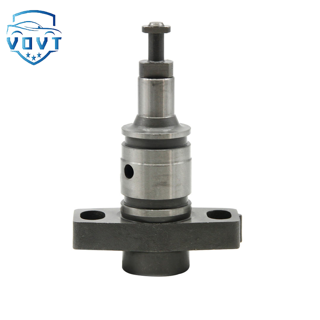
Made in China Fuel Injection Pump Plunger S1100 8.5mm Pump Elements Engine Accessories


products description
| Reference. Codes | S1100 |
| OE/OEM Codes | / |
| Application | / |
| MOQ | 5 PCS |
| Certification | ISO9001 |
| Place of Origin | China |
| Packaging | Neutral packing |
| Quality Control | 100% tested before shipment |
| Lead time | 7~15 working days |
| Payment | T/T, Paypal, Western Union or as your requirement |
What is the structure of the oil pump plunger?
Structural analysis of oil pump plunger: from core components to precision matching
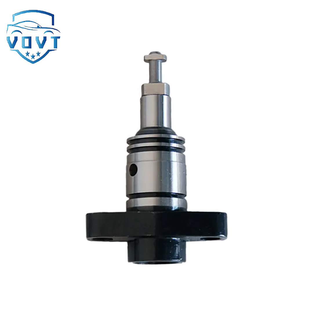
Plunger body: function and design details
As the key moving part of the oil pump, the plunger's body structure directly affects the pressure generation and flow control. Typical designs include:
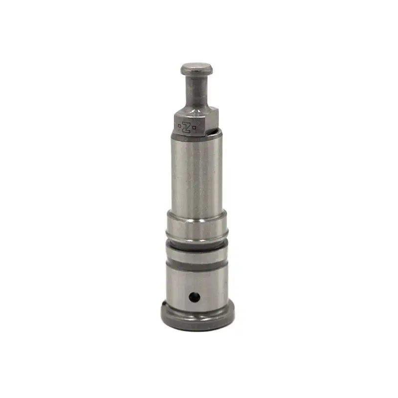
Top structure:
Hemispherical/conical top surface: reduce high-pressure fuel impact wear (such as diesel engine fuel injection pump plunger), some top surfaces have pressure relief grooves to optimize fuel injection atomization;
Flat top surface: commonly seen in hydraulic plunger pumps, with the valve plate to achieve oil suction and discharge switching.
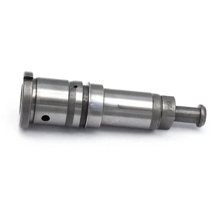
Middle body:
Cylindrical working surface: surface roughness Ra≤0.2μm, quenched or coated (such as chrome plating), hardness reaches HRC60+, resisting high-pressure friction;
Spiral groove/bevel groove: The diesel engine plunger adjusts the effective stroke by changing the relative position of the spiral groove and the plunger sleeve oil hole (as shown in Figure 1).
Bottom connection end:
Lug/ball head: connects to push rod or roller to transmit camshaft driving force (such as injection pump plunger driven by roller tappet);
Threaded interface: used to fix plunger connecting rod in hydraulic plunger pump and connect swash plate mechanism.
Plunger pair: core component with precision matching
The "pair" composed of plunger and plunger sleeve is the key to high-pressure sealing of oil pump, and its structural features are as follows:
Plunger sleeve:
Oil hole design:
Oil inlet hole and oil return hole: Diesel engine plunger sleeve usually has 1-2 oil holes, which are connected to the top surface of plunger when oil is inlet and connected through spiral groove when oil is return (as shown in Figure 2);
Positioning boss: fixed to the pump body by boss during installation to ensure accurate position of oil hole.
Inner hole accuracy:
Diameter tolerance is controlled at ±0.002mm, roundness ≤0.001mm, and the matching clearance with plunger is only 5-10μm, which needs to be processed by matching process (paired processing).
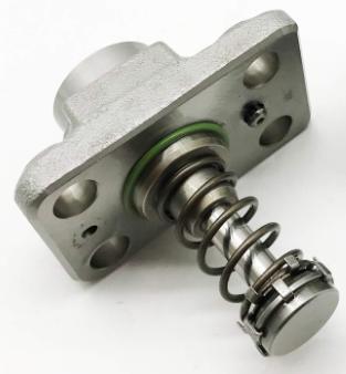
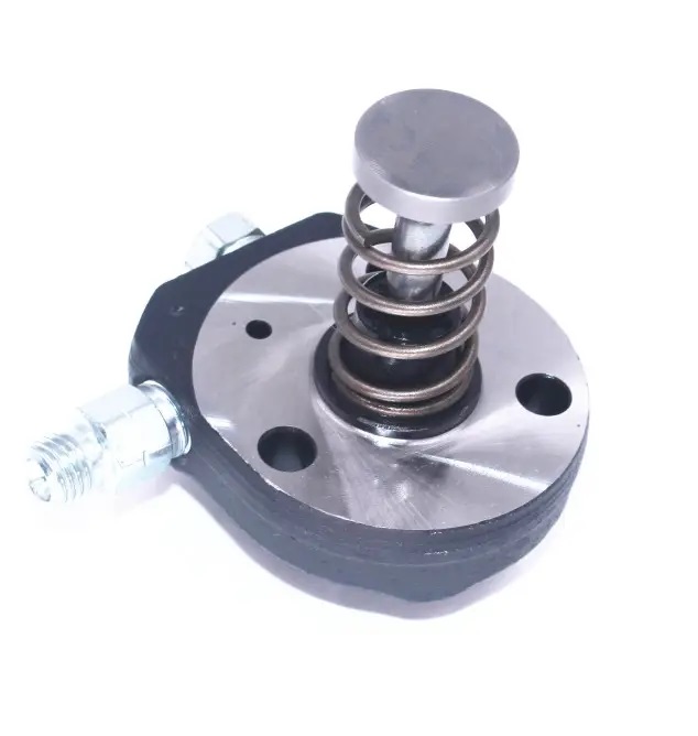
Oil outlet valve assembly:
Installation location: top of plunger sleeve, fixed by oil outlet valve seat;
Structural composition: valve core, valve seat, pressure relief ring, spring (as shown in Figure 3). When high pressure is applied, the valve core is pushed open to discharge oil. When the machine is shut down, the pressure relief ring cuts off the oil path to prevent fuel leakage.
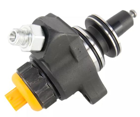
III. Adjustment mechanism: key component of oil quantity control
In the fuel pump, the plunger needs to cooperate with the adjustment mechanism to adjust the oil supply. Common structures include:
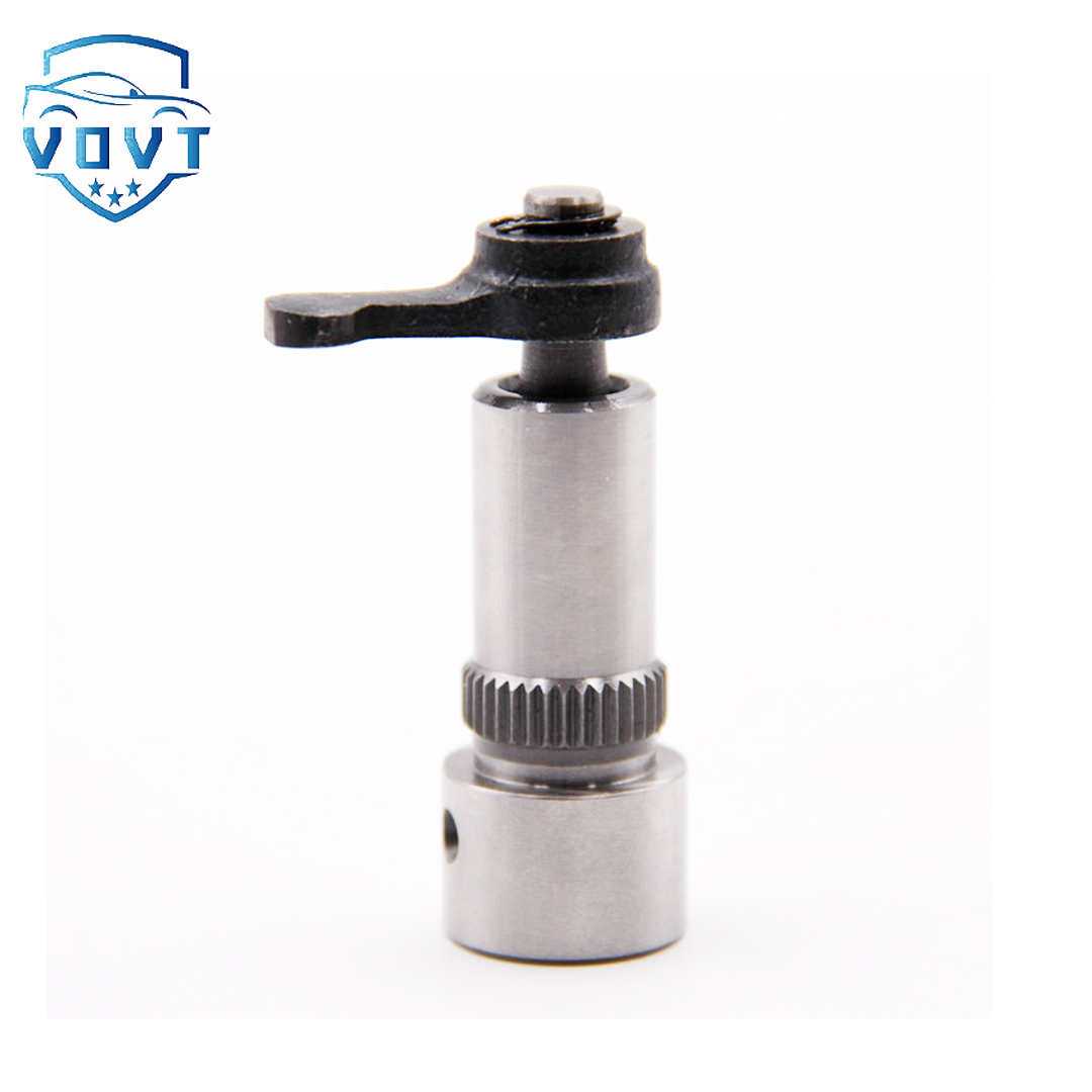
Rack-gear ring mechanism (as shown in Figure 4):
When the rack moves horizontally, it drives the gear ring to rotate, and the gear ring engages with the bottom of the plunger, changing the angle of the plunger spiral groove and adjusting the effective stroke;
Application scenario: traditional inline pump (such as Bosch A-type pump).
Fork-adjustment arm mechanism:
The fork drives the adjustment arm through the pull rod. The adjustment arm is fixed at the bottom of the plunger, pushing the plunger to rotate and changing the position of the spiral groove;
Application scenario: domestic II injection pump, some distribution pumps.
Solenoid valve control (electronic fuel injection system):
The mechanical adjustment mechanism is eliminated, and the opening and closing of the solenoid valve is controlled by the ECU to directly control the timing and amount of fuel supply of the plunger (such as the plunger of the common rail system).
Transmission and drive structure
The reciprocating motion of the plunger depends on the drive mechanism, and the transmission structure of different types of oil pumps is significantly different:
Camshaft drive (diesel fuel injection pump):
When the camshaft rotates, the plunger is pushed upward by the roller tappet, and the plunger spring resets downward (as shown in Figure 5);
The cam profile (such as tangential cam, function cam) determines the plunger movement speed and affects the injection pressure rise rate.
Swash plate drive (axial plunger pump):
The transmission shaft drives the cylinder body to rotate, and the plunger rotates with the cylinder body, while being affected by the inclination of the swash plate to perform axial reciprocating motion (as shown in Figure 6);
Adjusting the inclination of the swash plate can change the plunger stroke and realize variable pump displacement adjustment.
Eccentric drive (radial piston pump):
When the eccentric rotates, the plunger is pushed to reciprocate in the radial hole, and the oil suction and discharge are controlled by the distribution shaft (as shown in Figure 7).
Key matching and sealing design
Plunger-sleeve matching:
Adopt interference fit or extremely small clearance (5-10μm), rely on fuel or hydraulic oil to form oil film lubrication, and ensure high-pressure sealing;
Material matching: The plunger is often carburized bearing steel (such as GCr15), and the plunger sleeve is alloy cast iron (such as HT300), and the surface is nitrided.
Oil outlet valve seal:
The contact surface between the valve core and the valve seat is a conical surface (angle 3°-5°), which is ground to achieve line sealing, and the matching clearance between the pressure relief ring and the valve seat hole is ≤5μm.
Influence of materials and surface treatment on structure
Main body material:
20CrMnTi carburized and quenched (surface hardness HRC62-65, core HRC30-40), taking into account both wear resistance and impact resistance;
Hydraulic plunger can use 42CrMo, quenched + tempered (HRC45-50), adapt to alternating loads.
Surface coating:
Chromium plating (Cr) layer thickness 5-10μm, hardness HV1000+, anti-fuel corrosion;
PVD titanium nitride (TiN) coating, friction coefficient reduced by 30%, suitable for high-speed plungers (such as electronic injection systems).
By disassembling the structural components and matching relationship of the oil pump plunger, we can intuitively understand how it can achieve high-pressure fluid delivery through precision design. The structural evolution from mechanical adjustment to electronic control drive also reflects the development trend of oil pump technology towards high precision and intelligence.
Products categories
-

Diesel Fuel Pump Plunger 0941500618 For Excavator
-
Fuel Pump Plunger F01M100869 For Bosch CP1 Fuel...
-

Best Selling New Diesel Pump Plunger P388 Plung...
-

Brand New Diesel Fuel Injection Pump Plunger &#...
-

China Made New Diesel Pump Plunger A161 Plunger...
-

China Top New Diesel Pump Plunger 090150-7653 P...
-

China Top New Diesel Pump Plunger 2 418 455 542...
-
China Top New Diesel Pump Plunger PH9 Plunger B...
-
Common Rail Fuel Injection Pump Plunger 094150-...
-

Common Rail Injection Pump Plunger 094150-0330 ...
-
Common Rail Pump Plunger 294090-0080 294090-009...
-
Diesel Fuel Injection Pump Element Plunger 0901...
-
Diesel Fuel Pump Plunger 2418441001 for BENZ OM422
-
Diesel Injection Pump Plunger 2455-429
-

Diesel Pump Plunger PB202 For ASIMCO
-
Factory Direct Sales New Diesel Pump Plunger 51...


