
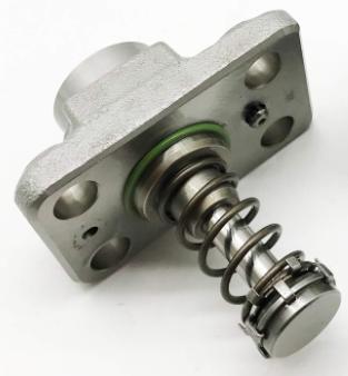
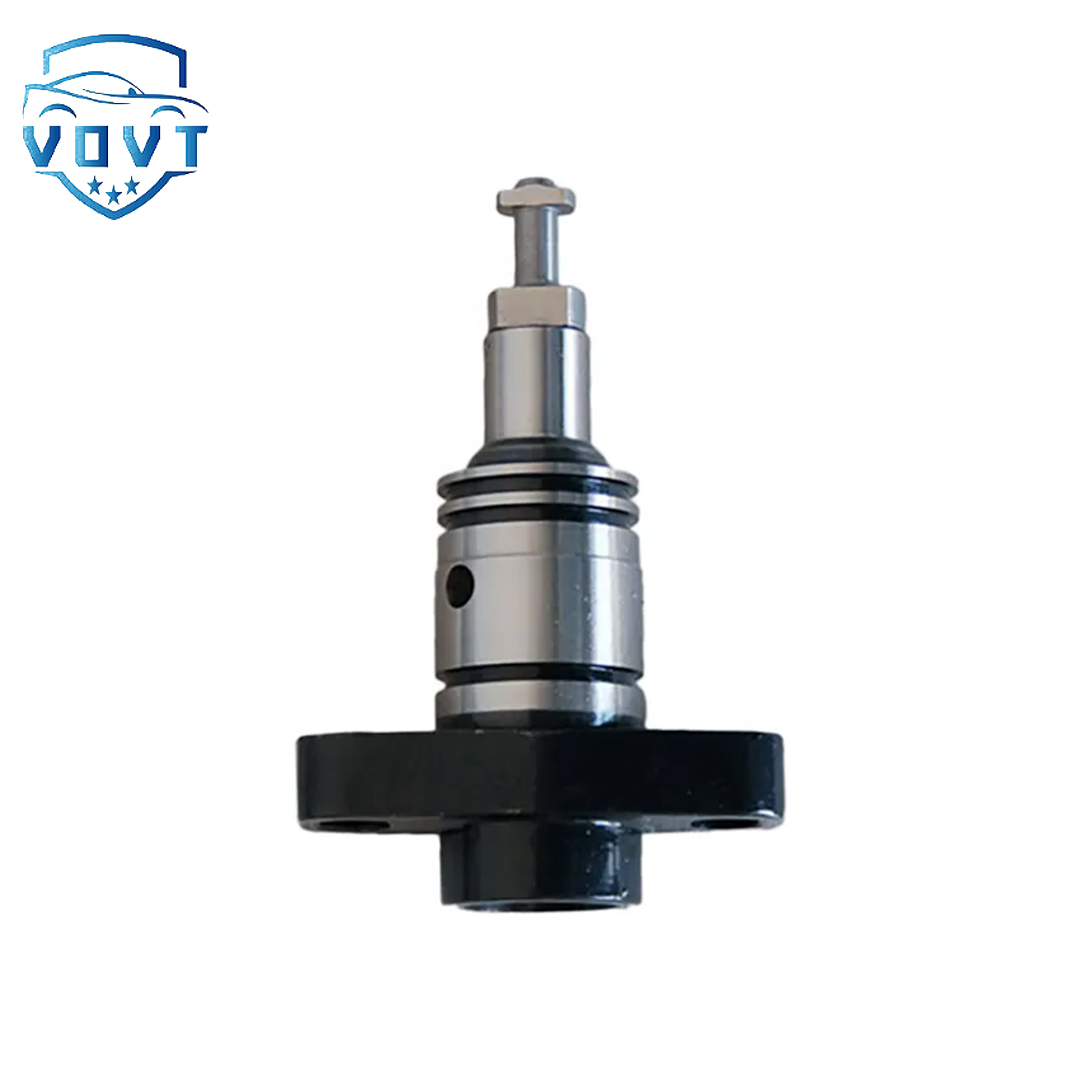
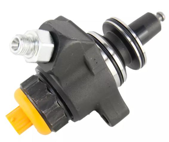
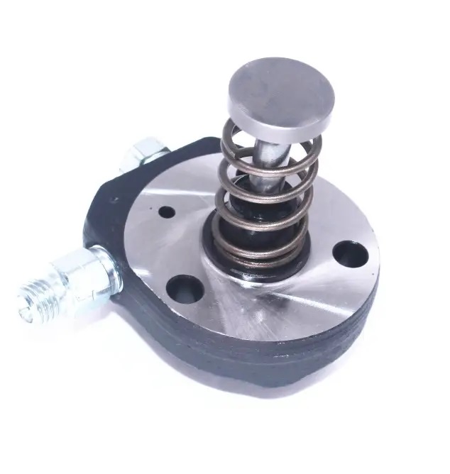
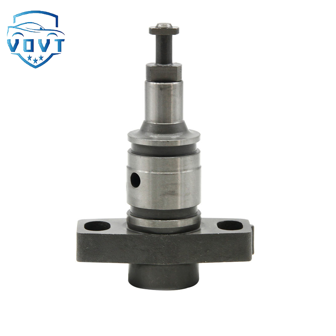
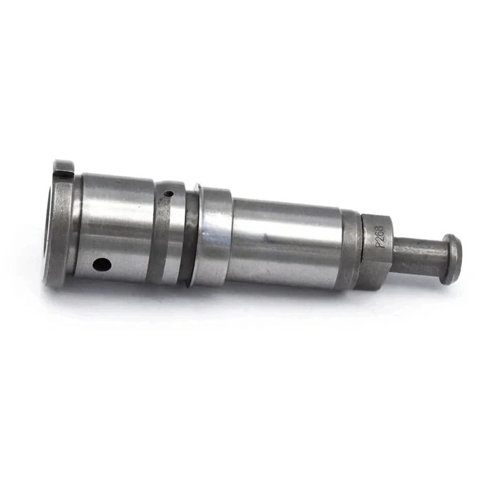
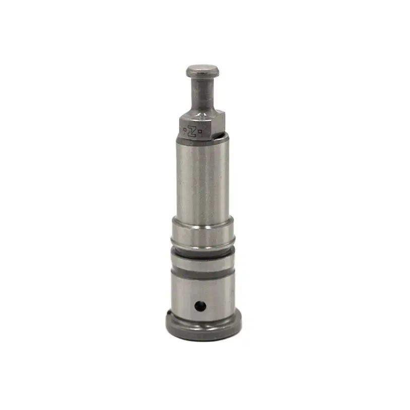
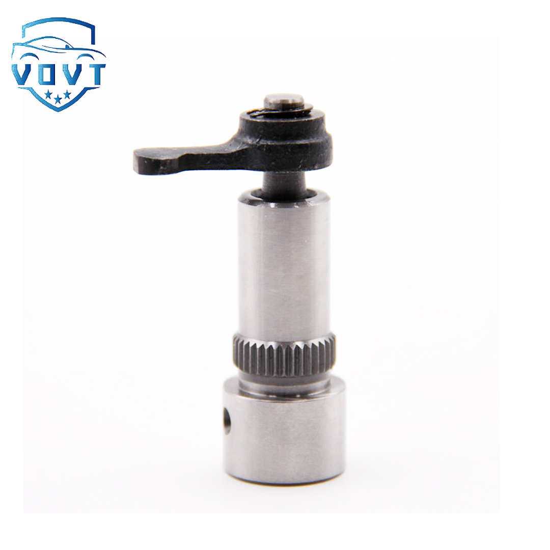
Made in China Fuel Injection Pump Plunger 1701 Pump Elements Engine Accessories


products description
| Reference. Codes | 1701 |
| OE/OEM Codes | / |
| Application | / |
| MOQ | 5 PCS |
| Certification | ISO9001 |
| Place of Origin | China |
| Packaging | Neutral packing |
| Quality Control | 100% tested before shipment |
| Lead time | 7~15 working days |
| Payment | T/T, Paypal, Western Union or as your requirement |
Application of plungers in automobile engines
The plunger is a core precision component in the fuel delivery system of an automotive engine, particularly a diesel engine. Its primary function is to pressurize, meter, and time the injection of fuel through reciprocating motion, directly impacting the engine's power, fuel economy, and emissions. The following provides a detailed introduction to its structure, operating principle, application scenarios, technical features, and development trends:
I. Basic Structure and Materials of the Plunger
Structural Components
The plunger is typically a cylindrical precision component consisting of a plunger head, plunger rod, and plunger tail:
The plunger head: Features an oblique or spiral groove that, in conjunction with the plunger sleeve, controls the timing of fuel inflow and outflow, achieving both fuel delivery timing and quantity adjustment.
The plunger rod: Its surface is precision ground and polished to ensure a tight fit with the plunger sleeve (typically with a clearance of 0.001-0.003mm), preventing fuel leakage.
The tail: Connects to the tappet or pushrod driven by the camshaft, receiving mechanical drive force to achieve reciprocating motion. Material Requirements
Due to the long-term exposure to high pressure (up to 100 MPa), high-frequency reciprocating motion (thousands of times per minute), and fuel erosion, the plunger must be made of high-strength, high-wear-resistant materials, such as:
Alloy structural steel (such as 38CrMoAlA) nitrided to achieve a surface hardness of HV900 or higher;
Powder metallurgy materials (such as high-speed steel-based powder alloys) sintered to enhance wear resistance.
II. Working Principle in the Engine (Taking a Diesel Engine as an Example)
The plunger is a core component of the fuel injection pump, and its operation directly determines the amount and timing of fuel injection:
Suction Phase: The camshaft rotates, causing the plunger to descend. The oil inlet port on the plunger sleeve opens, and fuel enters the plunger cavity under gravity or pump pressure.
Compression Phase: The cam lifts the tappet, causing the plunger to ascend, closing the oil inlet port. The plunger cavity volume decreases, compressing the fuel to a high pressure. When the pressure exceeds the injector opening pressure, the fuel enters the injector through the delivery valve and high-pressure fuel line, and is sprayed into the combustion chamber. Oil return adjustment: When the chute on the plunger head connects to the oil return hole on the plunger sleeve, high-pressure fuel is released back into the low-pressure oil circuit through the oil return hole, ending the oil compression phase. By rotating the plunger (controlled by the speed governor) to change the relative position of the chute and the oil return hole, the effective oil compression stroke can be adjusted, thereby varying the fuel delivery (e.g., low fuel delivery at idle, high fuel delivery at full load).
III. Application Differences in Different Engine Types
Diesel Engines
The plunger is a core component of in-line pumps (such as A-type and P-type pumps) and distributor pumps (such as VE pumps):
In-line pumps: Each cylinder has a corresponding plunger-sleeve assembly, with independent fuel delivery control. This provides high precision but a complex structure.
Distributor pumps: A single plunger delivers fuel to multiple cylinders through rotation and reciprocating motion. This compact design makes it suitable for small diesel engines. Gasoline Engines
Traditional carburetor engines do not require plungers. In modern electronically controlled gasoline engines, plungers are often used in high-pressure fuel pumps (such as those in direct injection engines). The plunger applies pressure to increase fuel pressure to 10-35 MPa, providing high-pressure fuel for direct injection into the cylinders.
IV. The Impact of the Plunger on Engine Performance
Power: The effective stroke of the plunger determines the fuel delivery rate. Insufficient stroke (e.g., wear leading to leakage) reduces the fuel injection rate and engine power.
Economy: Excessive clearance between the plunger and the plunger sleeve (exceeding 0.005mm) can cause fuel leakage, unstable fuel delivery, and increased fuel consumption (leakage of 1 drop/minute can increase fuel consumption by more than 5%).
Emissions: Deviations in the plunger's fuel delivery timing (e.g., wear leading to a change in the chute position) can cause abnormal injection advance angles, resulting in incomplete combustion and increased emissions such as HC and NOx. Reliability: A stuck plunger (due to impurities or poor lubrication) can interrupt fuel supply and cause engine stalling. Excessive wear can lead to insufficient fuel pressure, engine jitter, and difficulty starting.
V. Plunger Maintenance and Troubleshooting
Common Faults
Wear: Wear on the mating surface between the plunger and the plunger sleeve causes fuel leakage and pressure drop.
Stick: Fuel impurities or colloid deposits on the mating surface prevent the plunger from moving freely.
Corrosion: Sulfur and moisture in low-quality fuel can corrode the plunger surface, impairing wear resistance.
Maintenance Tips
Use clean fuel that meets standards and replace the fuel filter regularly to prevent impurities from entering.
Replace the injection pump lubricant as required to maintain plunger lubrication.
Regularly check the clearance between the plunger and plunger sleeve. Replace if the clearance exceeds the specified limit (typically, wear to 0.005mm or more requires replacement).
VI. Technological Development Trends
As engines evolve toward higher pressure, electronic control, and lighter weight, plunger technology is also undergoing continuous upgrades:
Higher Pressure: Plunger operating pressure has increased from the traditional 70 MPa to over 200 MPa (e.g., common rail systems), requiring the use of higher-strength materials (e.g., ceramic-coated plungers) and precision machining processes (e.g., ultra-precision grinding).
Electronic Control: Traditional mechanically controlled plungers are gradually being replaced by electronically controlled plungers, which utilize solenoid valves to control the oil return timing, enabling precise electronic control of fuel delivery and timing (e.g., electronically controlled inline pumps and electronically controlled distributor pumps).
Integration: The plunger is integrated with other fuel injection pump components (e.g., delivery valves and solenoid valves) to reduce leak points and improve system response speed.
Summary
As the "heart" of the engine's fuel supply system, the plunger's precision, wear resistance, and reliability are directly related to the engine's overall performance. With increasingly stringent automotive emissions regulations and advances in engine technology, plungers are evolving toward higher pressures, higher precision, and electronic control, becoming a key component in improving engine efficiency and environmental friendliness.
Products categories
-

Diesel Fuel Pump Plunger 0941500618 For Excavator
-
Fuel Pump Plunger F01M100869 For Bosch CP1 Fuel...
-

Best Selling New Diesel Pump Plunger P388 Plung...
-

Brand New Diesel Fuel Injection Pump Plunger &#...
-

China Made New Diesel Pump Plunger A161 Plunger...
-

China Top New Diesel Pump Plunger 090150-7653 P...
-

China Top New Diesel Pump Plunger 2 418 455 542...
-
China Top New Diesel Pump Plunger PH9 Plunger B...
-
Common Rail Fuel Injection Pump Plunger 094150-...
-

Common Rail Injection Pump Plunger 094150-0330 ...
-
Common Rail Pump Plunger 294090-0080 294090-009...
-
Diesel Fuel Injection Pump Element Plunger 0901...
-
Diesel Fuel Pump Plunger 2418441001 for BENZ OM422
-
Diesel Injection Pump Plunger 2455-429
-

Diesel Pump Plunger PB202 For ASIMCO
-
Factory Direct Sales New Diesel Pump Plunger 51...


