
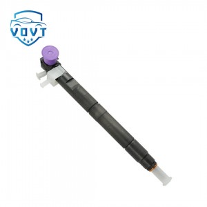
Hot Selling Fuel Injector Actuator Control Solenoid Valve for 4307545 Engine Parts


Products Description
| Reference Codes | 4307545 |
| Application | / |
| MOQ | 6 PCS |
| Certification | ISO9001 |
| Place of Origin | China |
| Packaging | Neutral packing |
| Quality Control | 100% tested before shipment |
| Lead time | 7~15 working days |
| Payment | T/T, L/C, Paypal, Western Union, MoneyGram or as your requirement |
Research on the structural characteristics, control technology and performance optimization of the injector solenoid valve
Abstract
As the core actuator of electronic fuel injection systems, the injector solenoid valve achieves precise metering and timed fuel injection through electromagnetic force-driven valve core movement. It is a key component that determines engine power, fuel economy, and emissions performance. This paper systematically explains the structure and operating principle of the injector solenoid valve, deeply analyzes its core technical indicators such as electromagnetic characteristics, dynamic response, and sealing performance, explores control strategies and performance optimization methods under different operating conditions, and, in light of the development trends of new energy vehicles, explores its future technological direction. This paper provides theoretical support for the research, development, and application of high-precision injector solenoid valves.
I. Introduction
As automotive engines evolve towards higher efficiency and lower carbon emissions, the precise control capabilities of electronic fuel injection systems have become a key technological breakthrough. As the bridge between the electronic control unit (ECU) and the mechanical actuator, the injector solenoid valve's response speed, control accuracy, and reliability directly impact fuel atomization quality and combustion efficiency. Traditional mechanical fuel injection systems are no longer able to meet China VI emission regulations and above. Electronically controlled injection technology based on high-speed solenoid valves can achieve control accuracy of injection timing within ±0.5°CA and injection volume within ±1%, becoming a standard feature in modern engines. In-depth research into the operating mechanism and performance optimization paths of injector solenoid valves is of great practical significance for promoting engine energy conservation and emission reduction.
II. Structure and Operating Principle of the Injector Solenoid Valve
2.1 Basic Structural Components
The injector solenoid valve primarily consists of a solenoid coil, armature, valve core, return spring, and sealing assembly:
The solenoid coil is made of densely wound enameled wire (typically 0.08-0.12mm copper wire with 1500-3000 turns). When energized, it generates electromagnetic force to drive the armature. Its resistance is typically 12-16Ω (2-3Ω for low-resistance models). Armature and valve core: These precision components are integrated and manufactured from low-carbon steel or iron-nickel alloy. Chrome-plated (5-10μm thick) to reduce wear, the valve core's conical surface mates with the valve seat to provide a fuel seal, with a clearance of 3-5μm.
Return spring: This provides a preload of 5-15N to ensure rapid closure of the valve core after power is removed. Spring stiffness deviation must be controlled within ±5% to ensure consistency.
Seal assembly: This includes an O-ring (fluororubber, temperature resistant from -40°C to 200°C) and a metal gasket to prevent leakage of high-pressure fuel (operating pressures up to 100-300MPa). 2.2 Working Process Mechanism
The operating cycle of the injector solenoid valve can be divided into three phases:
Opening Phase: The ECU outputs a drive current (peak current 8-15A, holding current 1-3A). The coil generates a magnetic field, causing the armature to move upward, overcoming the spring force. The valve core leaves the valve seat, and high-pressure fuel is atomized and sprayed through the nozzle. This process must complete within 0.3-0.8ms.
Holding Phase: A holding current is applied to the coil, balancing the electromagnetic force and the spring force. The valve core remains open. The injection duration is controlled by the ECU based on operating conditions (typically 0.5-20ms).
Closing Phase: The current is cut off, the magnetic field disappears, and the valve core returns to its closed position under the action of the spring force, terminating injection. The closing response time must be less than 0.5ms to prevent dripping.
III. Core Technical Indicators and Influencing Factors
3.1 Dynamic Response Characteristics
Dynamic response is a key indicator of solenoid valve performance, including opening time (t₁) and closing time (t₂):
Opening time is affected by coil inductance (10-30mH), electromagnetic force, and the mass of the moving parts. Optimizing the magnetic circuit design (such as adding a magnetic ring) can increase electromagnetic force by 20%, and using lightweight alloys (such as titanium) to manufacture the armature can reduce the moving mass by 30%, keeping t₁ below 0.4ms.
Closing time is primarily determined by spring stiffness and the damping of the moving parts. Experimental data shows that increasing the spring preload from 8N to 12N can shorten t₂ from 0.6ms to 0.4ms. However, an overly strong spring will increase opening energy consumption. 3.2 Sealing Performance
Under high pressure of 300 MPa, the sealing performance between the valve core and the valve seat directly affects injection accuracy:
The sealing surface adopts a conical line contact design (cone angle 60° ± 1°), with a surface roughness of Ra0.02μm or less. Liquid sealing is achieved through precision grinding.
Over long-term use, particulate matter in the fuel can cause wear on the sealing surface. When the wear exceeds 1μm, leakage (>0.5mm³ per cycle) may occur, resulting in excessive emissions.
3.3 Electromagnetic Compatibility (EMC)
Electromagnetic interference (EMI) generated during solenoid valve switching can affect ECU operation:
When the coil is de-energized, the back EMF can reach 200-500V. A parallel freewheeling diode or RC snubber circuit is required to suppress the spike voltage.
Shielding the coil leads with shielded wire can reduce radiated interference by over 40dB, meeting the ISO 11452 EMC standard.
IV. Control Strategy and Performance Optimization
4.1 Drive Current Optimization
A two-stage drive strategy is adopted:
Peak phase (0-0.3ms): A high current (10A) is applied to quickly establish the magnetic field and shorten the opening time.
Holding phase: The current is reduced to a low current (2A) to maintain the opening state and reduce the coil temperature rise (≤100K).
Experiments have shown that this strategy can reduce the solenoid valve's power consumption by 50% while also preventing performance degradation caused by coil overheating.
4.2 Structural Parameter Optimization
Multi-objective optimization based on finite element simulation:
Using Ansoft Maxwell software to analyze the magnetic circuit distribution, the number of coil turns and armature size were optimized, improving electromagnetic force uniformity by 15%.
The response surface methodology was used to optimize the matching relationship between the valve core taper angle and spring stiffness, increasing dynamic response speed by 20% while ensuring sealing.
4.3 Innovative Material Application
The coil bobbin is made of high-temperature-resistant PA66 + 30% glass fiber, capable of withstanding long-term operating temperatures of 150°C. The valve core surface is coated with a diamond-like carbon (DLC) coating, achieving a hardness exceeding HV2000 and improving wear resistance by three times, extending its service life from 100,000 cycles to 300,000.
V. Application Scenarios and Development Trends
5.1 Traditional Fuel Engines
In diesel engine electronically controlled common rail systems, high-speed solenoid valves enable multi-stage injection (pre-injection, main injection, and post-injection) with five injections per cycle, reducing NOx emissions by 30% and PM emissions by 40%. Application data from a commercial vehicle engine shows that the optimized solenoid valve reduces fuel consumption per 100 kilometers by 8%, meeting the China VIb emission standard.
5.2 New Energy Hybrid Systems
In P2 architecture hybrid vehicles, the solenoid valves must adapt to frequent engine start-stop conditions. By enhancing the fatigue resistance of the springs (using 50CrVA spring steel with a shot peening treatment), the start-stop cycle durability can be increased to over 100,000, meeting the requirements of hybrid vehicles. 5.3 Future Technology Directions
Intelligent: Integrating pressure sensors and position feedback devices enables closed-loop control, achieving injection volume accuracy of ±0.5%.
High-Pressure: Adapting to ultra-high-pressure injection systems up to 400 MPa requires the development of high-pressure-resistant electromagnetic materials and sealing structures.
Integrated: Integrated design with the injector nozzle reduces the high-pressure chamber and improves injection response speed by another 15%.
VI. Conclusion
Optimizing injector solenoid valve performance is a key breakthrough in improving overall engine performance. Through structural parameter optimization, innovative drive strategies, and material technology upgrades, dynamic response and sealing performance can be significantly improved to meet increasingly stringent environmental regulations. With the advancement of intelligent and integrated technologies, injector solenoid valves will evolve towards higher precision, higher reliability, and lower energy consumption, providing core support for the sustainable development of automotive powertrains.
Products categories
-

Professional Manufacture Common Rail Injector 2...
-
High Quality Common Rail Control Valve Set Asse...
-

High Quality New Common Rail Injector Control V...
-

Diesel Injector Fuel Injector 23670-0L070 Denso...
-
Professional Manufacture Diesel Fuel Injector A...
-

Hot Selling Fuel Injector Actuator Control Sole...


