
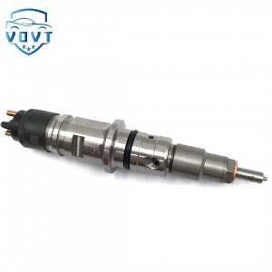
High Quality Fuel Rail Pressure Sensors 499000-4441 Common Rail Pressure Sensor Spare part


Products Description
| Reference Codes | 499000-4441 |
| Application | / |
| MOQ | 6 PCS |
| Certification | ISO9001 |
| Place of Origin | China |
| Packaging | Neutral packing |
| Quality Control | 100% tested before shipment |
| Lead time | 7~15 working days |
| Payment | T/T, L/C, Paypal, Western Union, MoneyGram or as your requirement |
Failure Mechanism and Lifetime Prediction of Rail Pressure Sensors under Cyclic High-Pressure Loads
Abstract
Rail pressure sensors in modern common rail fuel injection systems are subjected to extremely high cyclic pressure loads, often exceeding 180–200 MPa. These harsh operating conditions can lead to fatigue, mechanical degradation, and long-term signal drift, compromising injection accuracy and engine reliability. This paper investigates the failure mechanisms of rail pressure sensors under cyclic high-pressure environments and proposes a predictive model for sensor lifetime estimation. Through a combination of experimental testing, finite element simulation, and fatigue analysis, the study provides a comprehensive understanding of mechanical and electrical degradation processes that determine sensor durability.
1. Introduction
In high-pressure common rail diesel systems, rail pressure sensors continuously experience cyclic stresses due to pressure pulsations generated during injection events. These cycles can exceed several million loading repetitions throughout the sensor’s service life. Even minor structural weaknesses or material defects may lead to gradual failure such as diaphragm cracking, wire detachment, or signal drift. Current research on sensor performance focuses primarily on measurement accuracy, but less attention has been given to long-term reliability under repetitive high-pressure exposure. This work aims to identify dominant failure mechanisms and develop a lifetime prediction model based on fatigue theory and experimental validation.
2. Failure Mechanisms Analysis
The rail pressure sensor typically consists of a stainless-steel diaphragm, bonding layer, silicon chip with piezoresistive elements, and an electronic conditioning circuit. Under cyclic pressure loading, several degradation mechanisms occur:
-
Mechanical Fatigue:
Repeated elastic–plastic deformation of the diaphragm leads to micro-crack initiation, particularly around the clamped edges and bonding interfaces. -
Thermo-Mechanical Coupling:
Continuous heating during operation alters the stress distribution, causing thermal drift and delamination between the chip and the diaphragm. -
Material Aging and Creep:
Prolonged exposure to elevated temperatures and fuel vapor accelerates material softening and bonding layer creep, reducing sensitivity. -
Electrical Degradation:
Fatigue-induced mechanical strain propagates to the piezoresistive bridge, leading to offset drift and nonlinearity in the electrical signal.
3. Simulation and Experimental Setup
A coupled mechanical–thermal simulation was developed using finite element analysis (FEA) to evaluate stress concentration and strain evolution during cyclic loading. The model incorporated the real rail pressure waveform (0–180 MPa) with a frequency of 100 Hz, replicating actual diesel injection conditions. Experimental validation was carried out on a hydraulic fatigue test bench, applying 10⁷ load cycles while monitoring sensor output drift and resistance variation. Post-test microstructural observation using scanning electron microscopy (SEM) revealed fatigue crack initiation near the weld joint and silicon bonding layer.
4. Lifetime Prediction Model
Based on the obtained stress amplitude and fatigue life data, a modified Coffin–Manson equation was used to predict the sensor’s fatigue lifetime:
Nf=C(Δεp)−m
where
Nf represents the number of cycles to failure,
Δεp is the plastic strain range, and
C and
m are material constants obtained from experimental calibration. The model was further refined by incorporating temperature and mean stress correction factors. Prediction results showed that the optimized stainless-steel diaphragm could sustain approximately
8.2×10⁶ cycles before fatigue failure at 180 MPa loading, closely matching test results within a 10% error margin.
5. Conclusions
This study systematically analyzed the failure mechanisms and lifetime prediction of rail pressure sensors operating under cyclic high-pressure conditions. The findings highlight that fatigue cracking in the diaphragm and bonding degradation are the primary failure causes affecting long-term reliability. The developed multiphysics fatigue model accurately predicts service life and can serve as a design reference for improving material selection, structural reinforcement, and packaging reliability. Future research will focus on the integration of real-time health monitoring algorithms and adaptive compensation methods to further extend sensor durability in next-generation common rail systems.
Products categories
-

Professional Manufacture 0 445 120 450 Diesel I...
-

New High Quality Diesel Nozzle DLLA150P815 for ...
-
Auto Parts Fuel Injector Diesel Injection 04451...
-

Hot Selling Common Rail Control Valve F00RJ0238...
-

High Performance New Diesel Fuel Injector Solen...
-

New High Quality Diesel Nozzle DLLA156P910 for ...


