
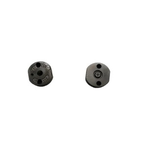
High Quality Fuel Rail Pressure Sensors 029600-0580 Common Rail Pressure Sensor Spare part


Products Description
| Reference Codes | 029600-0580 |
| Application | / |
| MOQ | 6 PCS |
| Certification | ISO9001 |
| Place of Origin | China |
| Packaging | Neutral packing |
| Quality Control | 100% tested before shipment |
| Lead time | 7~15 working days |
| Payment | T/T, L/C, Paypal, Western Union, MoneyGram or as your requirement |
CFD–FEA Coupled Analysis of Flow–Magnetic Interaction in High-Pressure Injector Electromagnetic Valves
Abstract
Electromagnetic valves in high-pressure diesel injectors operate under strong interactions between internal fuel flow, magnetic field distribution, and mechanical deformation. Traditional single-physics analysis—considering electromagnetic actuation, fluid flow, or structural stress independently—fails to accurately predict the dynamic response and control precision under real operating conditions. This study establishes a CFD–FEA coupled multiphysics model to investigate the mutual influence of fuel flow, magnetic field, and structural deformation within high-pressure injector electromagnetic valves. The objective is to reveal the flow–magnetic coupling mechanisms affecting valve response time, pressure stability, and energy efficiency, thereby guiding optimization for high-frequency operation and long-term reliability.
1. Introduction
As fuel injection systems advance toward ultra-high pressures (250–300 MPa) and rapid response cycles, the electromagnetic control valve (EMV) becomes the key determinant of injector precision and durability. The internal transient flow generates complex hydrodynamic forces and cavitation near the valve seat, while the solenoid coil produces a strong magnetic field interacting with ferromagnetic materials in the armature and core. These coupled physical fields alter each other dynamically: magnetic force modifies valve displacement and local flow geometry, while flow-induced pressure oscillations and fluid temperature changes affect coil current and magnetic permeability. Quantifying this bidirectional coupling is essential for predicting valve dynamics accurately.
2. Methodology
A fully coupled CFD–FEA–magnetic simulation framework was developed using ANSYS Fluent and Maxwell through system-level co-simulation. The model consists of:
-
Electromagnetic domain: transient coil excitation modeled with eddy-current and magnetic saturation effects; nonlinear B–H curves were applied for soft magnetic materials.
-
Fluid domain: incompressible turbulent flow of diesel fuel with cavitation model (Schnerr–Sauer), capturing vapor formation and collapse near the seat and orifice regions.
-
Structural domain: elastic deformation of the valve needle and armature assembly under pressure and magnetic forces.
Dynamic mesh and fluid–structure coupling were implemented through Fluent’s user-defined functions (UDFs) to account for moving boundaries during valve opening/closing. The magnetic field solution was iteratively updated to reflect deformation-induced gap variation. Boundary conditions replicated injector operation: upstream pressure 200–300 MPa, downstream pressure 5 MPa, and coil excitation current up to 6 A with 0.3–1 ms pulse width.
3. Results and Discussion
Simulation results reveal several critical flow–magnetic coupling behaviors:
-
Magnetic–hydraulic interference: The electromagnetic attraction reduces armature–core gap size, compressing the fluid cavity and inducing local pressure surges. These surges alter the net hydraulic force on the needle, delaying or advancing opening response depending on current waveform.
-
Cavitation–magnetic feedback: Cavitation formation near the seat generates pressure fluctuations of up to ±20 MPa, introducing periodic perturbations in the magnetic gap. This dynamic gap variation causes corresponding fluctuations in magnetic force (≈3–5%), affecting response stability.
-
Thermal–magnetic coupling: Viscous heating from high-velocity fuel jets (up to 100 °C locally) slightly reduces magnetic permeability and coil conductivity, leading to a 2–3% decline in peak magnetic force during continuous operation cycles.
-
Deformation field interaction: Structural deformation of the armature and needle (on the order of 1–5 μm) changes the effective air-gap distribution and contact area, which in turn modifies both the local flow pattern and the magnetic flux density near the pole edges.
A parametric study indicates that optimizing the armature thickness and valve seat chamfer reduces hydrodynamic interference and improves opening stability. Reducing magnetic saturation in the core through material selection or flux-guiding design enhances energy efficiency by 6–8%. Furthermore, incorporating a damping groove near the seat mitigates pressure oscillations and improves response repeatability under high-frequency (up to 1 kHz) operation.
4. Validation
Experimental validation was performed using a transparent injector test rig equipped with a laser displacement sensor and high-speed pressure transducers. The simulated valve lift, pressure waveforms, and coil current profiles showed good agreement with measurements (R² > 0.94). The model successfully predicted transient phenomena such as pressure overshoot and hysteresis in the force–displacement curve.
5. Conclusions
The CFD–FEA coupled analysis demonstrates that the dynamic interaction between magnetic actuation and internal fuel flow is a dominant factor influencing valve precision and stability. Ignoring this coupling can cause up to 15% error in predicting response time or peak force. The results emphasize the need for integrated multiphysics modeling in the design of next-generation electromagnetic valves for high-pressure injectors. The established approach can also be extended to other high-speed electro-hydraulic systems requiring accurate flow–field and actuation interaction prediction.
Products categories
-

Made in China Diesel Injector Repaire Kits for ...
-

New High Quality Diesel Injector 20R-8060 20R-8...
-
Fuel Injection Valve Plate 295040-6120 for Dies...
-
Made In China Diesel Injector Repaire Kits for ...
-

Hot Selling Fuel Injector Actuator Control Sole...
-

New High Quality Diesel Nozzle L131PBA for Inje...


