
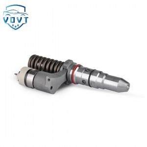
Genuine Quality Diesel Injector Repair Kit Adjusting Shim 0.050MM Injector Parts Engine Parts Auto Parts


products description
| Reference. Codes | 0.050MM |
| OE/OEM Codes | / |
| Application | Injector Repair Kits |
| MOQ | 4PC |
| Certification | ISO9001 |
| Place of Origin | China |
| Packaging | Neutral packing |
| Quality Control | 100% tested before shipment |
| Lead time | 7~15 working days |
| Payment | T/T, L/C, Paypal, Western Union or as your requirement |
Key points for selecting and installing adjusting gaskets
I. Key Points for Adjustment Shim Selection
1.1 Based on Injector Model and Parameters
Different injector models have significantly different requirements for adjustment shim specifications, so they must be strictly matched to the model. For example, the Bosch CRIN2 injector has an armature lift adjustment shim thickness range of 0.950-1.684mm, with an accuracy of 0.004mm per step. Other models may use completely different specifications. Also, refer to the injector's technical manual for performance parameters, such as valve spring force and armature lift settings, to ensure that the selected shim maintains critical parameters within the allowable tolerance range (typically ±3-±20 microns).
1.2 Based on Accurate Measurement Data
Key parameters must be measured using specialized equipment before selection:
Armature lift: Measured using a laser displacement sensor. If the measured value is 58 microns (CRIN series standard: 55 microns), a 0.003mm thick shim should be used for compensation.
Needle lift: Measured using a microscopic method. If the measured value exceeds the standard range of 200-350 microns, calibrate by increasing or decreasing the shim thickness.
Spring force: Measured using a pressure sensor. Shim thickness is selected based on the deviation. If the measured spring force is 62N (standard: 58N), the shim should be thinned to reduce the preload.
1.3 Considering Compatibility with the Operating Environment
For high-temperature, high-pressure operating conditions (such as diesel engines), high-temperature-resistant alloy shims are preferred. For hybrid systems with frequent starts and stops, composite shims with excellent fatigue resistance should be selected. Corrosion resistance requirements should also be considered in special environments. For example, chrome-plated adjustment shims can be used for marine engine injectors.
II. Key Points for Installing Adjustment Shims
2.1 Precise Installation Position
Different types of gaskets have strict installation position requirements:
Valve spring adjustment shims must fit snugly against the spring retainer, ensuring they are concentric with the spring axis.
Buffer lift shims (clamp-shaped) must be inserted into the dedicated slot, with the opening aligned with the valve body's positioning mark.
Needle lift shims must be placed on the precise contact surface between the needle valve and the actuator.
Before installation, check the assembly drawings and use a positioning fixture to assist with alignment to avoid parameter inaccuracies due to positional deviation.
2.2 Surface Cleaning and Condition Inspection
Before installation, clean the gasket and contact surfaces with anhydrous ethanol to remove oil, metal debris, and other impurities. Ultrasonic cleaning (300W power, 3 minutes) may be used if necessary. Also check the condition of the gaskets:
Surface flatness: Use a micrometer to check; the flatness tolerance must be ≤0.002mm.
Edge condition: No burrs or curling. Lightly sand with 1200-grit sandpaper if necessary.
Material integrity: No rust for metal gaskets, no cracks for composite gaskets.
2.3 Installation Precautions
Use specialized tools (such as tweezers or vacuum cups) to avoid direct finger contact and oil contamination. Apply even pressure during installation. Avoid knocking or tilting the gasket to prevent deformation. For multi-layer gaskets, install them sequentially. Apply specialized grease (such as silicone-based high-temperature grease) between each layer to reduce wear. A secondary inspection should be performed after installation. Use an endoscope to confirm that the gaskets are not dislodged. If necessary, perform a test run (run at a low speed of 300 rpm for 5 minutes). 2.4 Post-Installation Parameter Recalibration
After installation, key parameters must be re-tested:
Armature lift deviation should be ≤ ±5 microns
Spring force fluctuation should be controlled within ±3N
Needle valve response time must meet technical standards (typically ≤ 0.8ms)
If any abnormal parameters are detected, immediately shut down the machine for inspection to eliminate potential faults caused by improper gasket installation.
Products categories
-

Diesel Injector Fuel Injector 5284016 Denso Inj...
-
Auto Parts Fuel Injector Diesel Injection 249-0...
-

New High Quality Diesel Injector 249-0708 10R-2...
-
China Manufacturer Wholesale Price Diesel Engin...
-

Common Rail Diesel Fuel Injector Nozzle M0019p1...
-

New High Quality Diesel Nozzle DLLA127P944 for ...


