
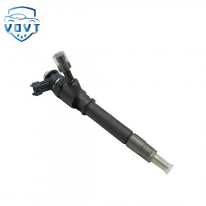
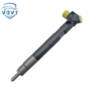
Genuine Quality Diesel Injector Repair Kit 23670-0E060 Injector Parts Engine Parts Auto Parts


products description
| Reference. Codes | 23670-0E060 |
| OE/OEM Codes | / |
| Application | Injector Repair Kits |
| MOQ | 4PC |
| Certification | ISO9001 |
| Place of Origin | China |
| Packaging | Neutral packing |
| Quality Control | 100% tested before shipment |
| Lead time | 7~15 working days |
| Payment | T/T, L/C, Paypal, Western Union or as your requirement |
Diesel Injector Repair Kits: Critical Components for Diesel Engine Repair
Preparation details before installation
Parts cleaning and inspection
Use filtered diesel or special cleaning agent to clean the parts to be installed (such as needle valve, valve seat, and nozzle pair). Cotton yarn or chemical fiber cloth (easy to leave residual fibers) is prohibited. Special lint-free wiping paper is required;
Check the integrity of the repair kit accessories: whether the seals (O-rings, copper pads) are damaged or aged (such as cracks or hardness changes in fluororubber rings), whether the spring elasticity is uniform (the compression amount of the new and old springs can be compared), and whether there are scratches or rust on the surface of the needle valve.
Installation environment and tool specifications
Build a dust-free working area (such as laying clean rubber pads) to avoid operating in the open air or dusty environments;
Use tools such as torque wrenches (accuracy ±2%) and special sockets. Adjustable wrenches are prohibited (easy to cause component deformation), and tools must be cleaned with diesel in advance.
Model Adaptation Confirmation
Check the repair kit model and the injector model (such as Bosch CRIN2 and CRIN3 series repair kits are not interchangeable), and focus on checking whether the needle valve length and seal size match to avoid leakage due to specification errors.
Key details in the assembly process
Seal installation tips
Before installing the O-ring, apply a thin layer of clean engine oil (no butter is allowed, which is easy to react with diesel), and ensure that it is embedded in the groove without twisting;
Metal seals such as copper pads need to be replaced at one time, and align the positioning holes during installation to avoid deflection (otherwise it will cause fuel leakage and may cause fire under high pressure).
Assembly of needle valve and injector nozzle parts
When assembling the needle valve, the needle valve body must be placed vertically, and tilting and knocking is prohibited (it is easy to scratch the mating surface). The needle valve can be gently rotated to make it slide naturally (normally there should be no sticking feeling);
When installing the injector cap, first tighten it by hand until it fits, and then tighten it with a wrench to the specified torque (such as 15-25N・m, depending on the model) in 2-3 times to avoid deformation of the thread due to one-time tightening.
Installation of spring and control components
The spring needs to be assembled in the original direction (some springs have directionality, such as one end is ground flat for positioning), and ensure that both ends fit together without skew;
The solenoid valve assembly of the electronic control injector needs to pay attention to the plug wiring sequence to avoid reverse connection (which may burn the coil), and the wiring terminals need to be clean and free of oxidation.
Verification details after installation
Sealing test
Use special equipment to pass fuel 50-100bar lower than the injection pressure into the injector (such as the standard injection pressure of 2000bar, the test pressure is set to 1900bar), hold for 10 seconds, and observe whether there is leakage on each sealing surface (such as the connection between the tight cap and the injector nozzle, the valve body and the pump body).
Mechanical parameter calibration
Use a dial indicator to measure the needle valve lift (such as the standard value of 0.3-0.5mm). If the deviation exceeds 0.05mm, it needs to be reassembled;
Adjust the preload of the pressure regulating spring to ensure that the opening pressure of the injector meets the original factory standard (such as 180-200bar). Deviations exceeding ±5bar will cause poor atomization.
Dynamic injection verification
Install on the test bench and test the injection volume under different working conditions (such as idle speed, rated speed). The deviation of the injection volume in each cycle must be ≤3%;
Observe the spray form: the multi-hole injector must spray evenly at each hole without deflection or oil beam merging, otherwise the needle valve may be installed skewed.
Fourth, finishing and protection details
Residual fuel cleaning
After assembly, use compressed air (≤0.3MPa) to blow away the residual impurities in the oil channel to avoid clogging the spray hole during startup.
Marking and recording
Mark the installation date and repair kit model on the injector housing for subsequent traceability;
Record the verification data (such as opening pressure, injection volume deviation) to form a maintenance file.
Initial operation specifications after installation
After the engine is started, run at idle speed for 5-10 minutes (immediate high-load operation is prohibited) to observe whether there is any abnormal sound or leakage;
After the engine is hot, check the torque of the injector fixing bolt again (thermal expansion and contraction may cause loosening), and tighten it according to the specified value.
Control of these details can effectively reduce more than 90% of injector failures (such as leakage, sticking, and poor atomization) caused by improper assembly, and is the core guarantee for maximizing the performance of the repair kit.
Products categories
-
View larger image Add to Compare Share Auto Pa...
-

High Efficiency Common Rail Diesel Fuel Injecto...
-

Low Price Good Quality Repair Kit 0 445 120 463...
-
High Quality Diesel Injector 28307309 Fuel Inje...
-

New High Quality Diesel Nozzle DLLA149P2216 for...
-

High Efficiency Fuel Injector Diesel Pump Injec...


