
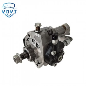
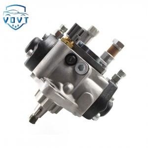
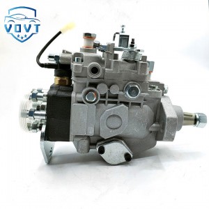
Diesel Fuel Injection Pump P5594766 V81CF304 Engine Auto Engine Part


products description
| Reference Code | P5594766 V81CF304 |
| MOQ | 1 PCS |
| Certification | ISO9001 |
| Place of Origin | China |
| Packaging | Neutral packing |
| Quality Control | 100% tested before shipment |
| Lead time | 7~15 working days |
| Payment | T/T, Western Union, Money Gram, Paypal, Alipay, Wechat |
Multi-dimensional exploration and development prospects of oil pumps
I. Introduction
Oil pumps, the powerhouse of fluid transport systems, are widely used in industries such as industry, agriculture, and transportation. Their fundamental operating principle is to transform the volume of the pump chamber through mechanical motion, converting mechanical energy into pressure and kinetic energy, thereby transporting the fluid. Although different types of oil pumps vary in structure, they all follow this basic principle, differing only in their specific implementation.
II. Working Principle of Positive Displacement Oil Pumps
2.1 Working Principle of Plunger Pumps
A plunger pump consists of a plunger, cylinder, and port plate. During operation, a motor drives the cylinder to rotate. The plunger rotates within the cylinder, moving back and forth linearly under the action of a swash plate. As the plunger extends outward, the volume of the sealed chamber formed by the plunger and cylinder increases, reducing the pressure within the chamber to below that of the suction chamber. The pressure differential causes the suction valve to open, drawing fluid into the sealed chamber, completing the suction process. As the cylinder continues to rotate, the plunger retracts inward under the force of the swash plate, reducing the volume of the sealed chamber. The fluid within is compressed, increasing the pressure. When the pressure exceeds the pressure in the discharge chamber, the discharge valve opens, discharging the high-pressure fluid and achieving oil pressure.
A plunger pump regulates flow by changing the plunger's stroke length or the cylinder's rotational speed. For example, in an axial piston pump, the reciprocating stroke of the plunger can be adjusted by changing the swash plate's tilt angle. A larger tilt angle results in a longer stroke and greater displacement, while a smaller tilt angle results in a smaller displacement. This adjustment method enables plunger pumps to achieve precise flow control over a wide range, making them suitable for high-pressure, high-flow applications, such as hydraulic systems in construction machinery.
2.2 Gear Pump Operating Principle
A gear pump consists of a pair of meshing gears, a pump housing, and end caps. The two gears are mounted on a driving shaft and a driven shaft, respectively. The driving shaft is driven by a motor, which in turn rotates the driven shaft in the opposite direction. On one side of the gear meshing area, as the gears rotate, the tooth grooves gradually disengage, increasing the volume of the space and creating a partial vacuum. Fluid from the oil tank, under atmospheric pressure, enters the tooth grooves through the oil intake port, completing the oil suction. As the gears carry the fluid from the tooth grooves to the other side of the meshing area, the tooth grooves gradually engage, reducing the volume of the space and squeezing the fluid out through the oil discharge port, achieving oil pressure.
The flow rate of a gear pump depends on the gear module, number of teeth, tooth width, and rotational speed. Due to the clearance between gears, a small amount of leakage occurs, affecting the pump's volumetric efficiency. To reduce leakage, gear pumps typically use a clearance compensation device, such as a floating sleeve inside the end cap. High-pressure oil from the discharge chamber pushes the sleeve against the gear end face, reducing the end face clearance and improving sealing performance. Gear pumps have a simple structure and reliable operation, making them suitable for low-pressure, medium-flow applications, such as machine tool lubrication systems.
2.3 Working Principle of Vane Pumps
Vane pumps include single-acting and double-acting vane pumps. A single-acting vane pump consists of a rotor, stator, vanes, and pump body. The inner surface of the stator is circular, and the rotor and stator are not concentric, resulting in an eccentricity. As the rotor rotates, the vanes press against the inner surface of the stator under the action of centrifugal force and pressurized oil. As the rotor rotates, the volume of the sealed chamber formed by the vanes, rotor, and stator changes with the rotor's position. As the sealed chamber moves from its minimum to maximum volume, the pressure decreases, drawing fluid from the suction port. As the sealed chamber moves from its maximum to its minimum volume, the pressure increases, and fluid is discharged through the discharge port. By varying the size and direction of the eccentricity, flow rate regulation and bidirectional oil supply can be achieved.
A double-acting vane pump has an elliptical inner surface of the stator, and the rotor and stator are concentric, with two suction and two discharge zones. As the rotor rotates, the vanes extend under the action of centrifugal force, causing the sealed chamber volume to alternately increase and decrease, completing the oil suction and discharge processes. Double-acting vane pumps offer uniform flow, minimal pulsation, and high volumetric efficiency, making them suitable for medium-pressure, medium-flow hydraulic systems, such as those used in injection molding machines.
III. Working Principle of Powered Oil Pumps
3.1 Working Principle of Centrifugal Pumps
A centrifugal pump consists of an impeller, pump casing, suction pipe, and discharge pipe. The impeller is mounted on the pump shaft and driven by a motor to rotate at high speed. As the impeller rotates, the blades drive the fluid along with it. Centrifugal force causes the fluid to move from the center of the impeller toward the periphery, gradually increasing its velocity and pressure until it enters the pump casing at a higher velocity. The flow path in the pump casing is volute-shaped. The fluid decelerates within the pump casing, converting kinetic energy into pressure energy, further increasing its pressure before being discharged through the discharge pipe. Simultaneously, a low-pressure area is created at the center of the impeller due to the ejection of fluid. Fluid from the reservoir, under atmospheric pressure, enters the center of the impeller through the suction pipe, achieving continuous water suction.
The flow rate of a centrifugal pump is related to the impeller diameter and speed, while the head depends on the impeller speed and diameter. To prevent cavitation within the pump (caused by low pressure causing vaporization of the fluid, which creates bubbles and causes impact and corrosion when the bubbles burst), centrifugal pumps must be installed with the suction height within the allowable range and the suction pipe must be airtight. Centrifugal pumps offer a simple structure, high flow rates, and ease of operation, making them widely used in agricultural irrigation, urban water supply, and drainage systems.
3.2 Working Principle of Axial Flow Pumps
Axial flow pumps consist of an impeller, pump casing, and guide vanes. The impeller is equipped with multiple blades, similar to a propeller. The motor drives the impeller at high speed, and the blades exert axial thrust on the fluid, propelling it axially. After entering the impeller, the fluid gains energy from the blades, which is converted to pressure energy by the guide vanes before being discharged from the pump outlet. Axial flow pumps offer high flow rates and low head, making them suitable for high-flow, low-head applications, such as river pumping and large pumping stations.
Flow rate regulation in axial flow pumps can be achieved by changing the blade angle, resulting in variable-vane axial flow pumps. Changing the blade angle alters the thrust exerted on the fluid, thereby varying the flow rate. This regulation method is highly efficient and can maintain high operating efficiency within a larger flow range.
Products categories
-

Diesel Fuel Injection Pump T73208235 Engine Aut...
-
High Quality Diesel Injector Pump 092000-5410 D...
-

Diesel Fuel Injection Pump MT040 Engine Auto En...
-
High Quality HP3 High Pressure Pump 294000-2690...
-
High-Quality Diesel Fuel Injection VE Pump 0460...
-

Diesel Fuel Injection VE Pump 0460426369 0 460 ...


