
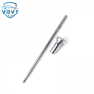
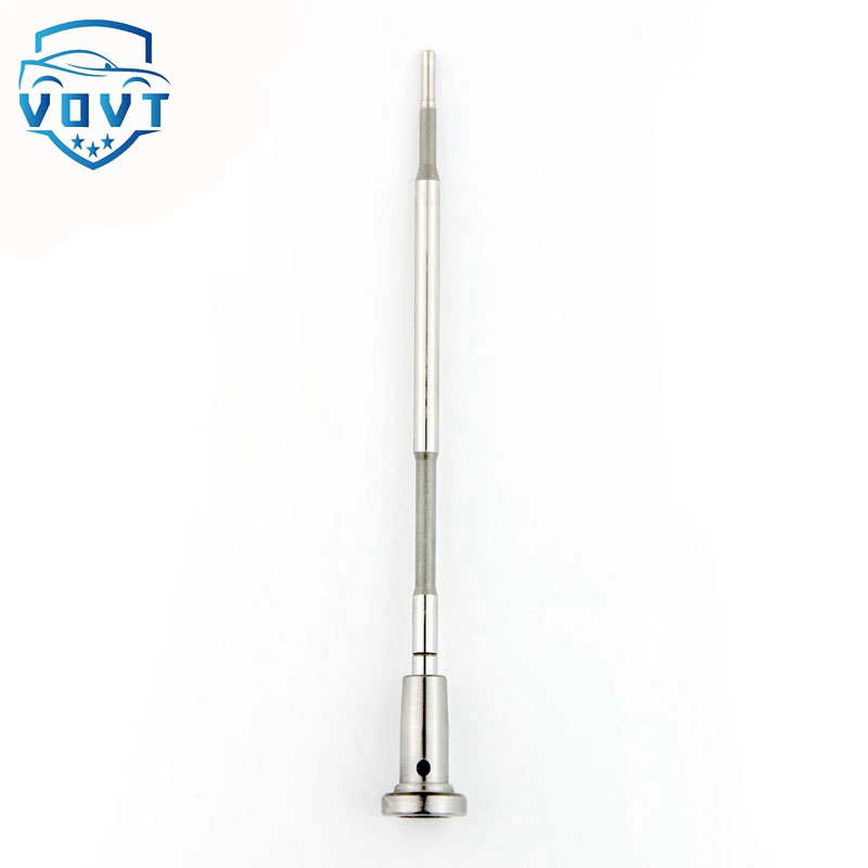
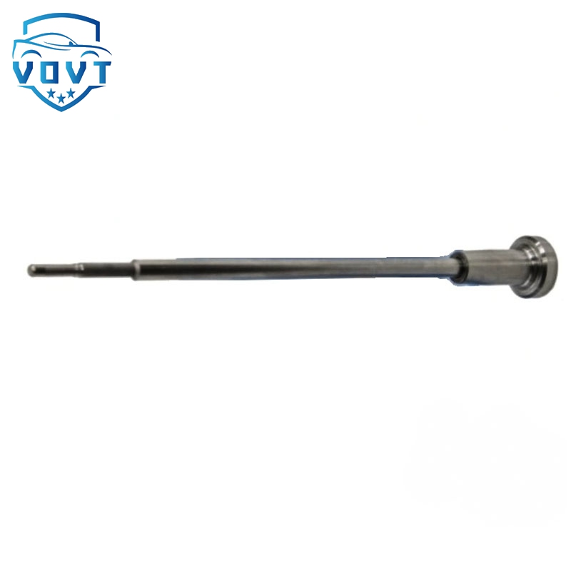
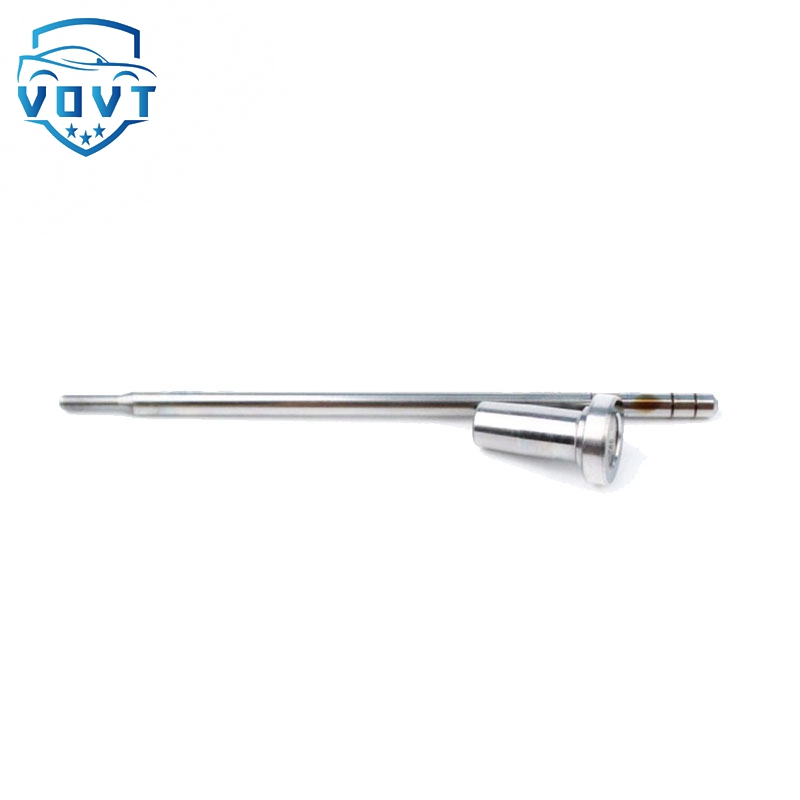
China Made Brand New Common Rail Fuel Injector F00VC01055 Control Valve Assembly for Injector 0445110222 0445110223


products detail
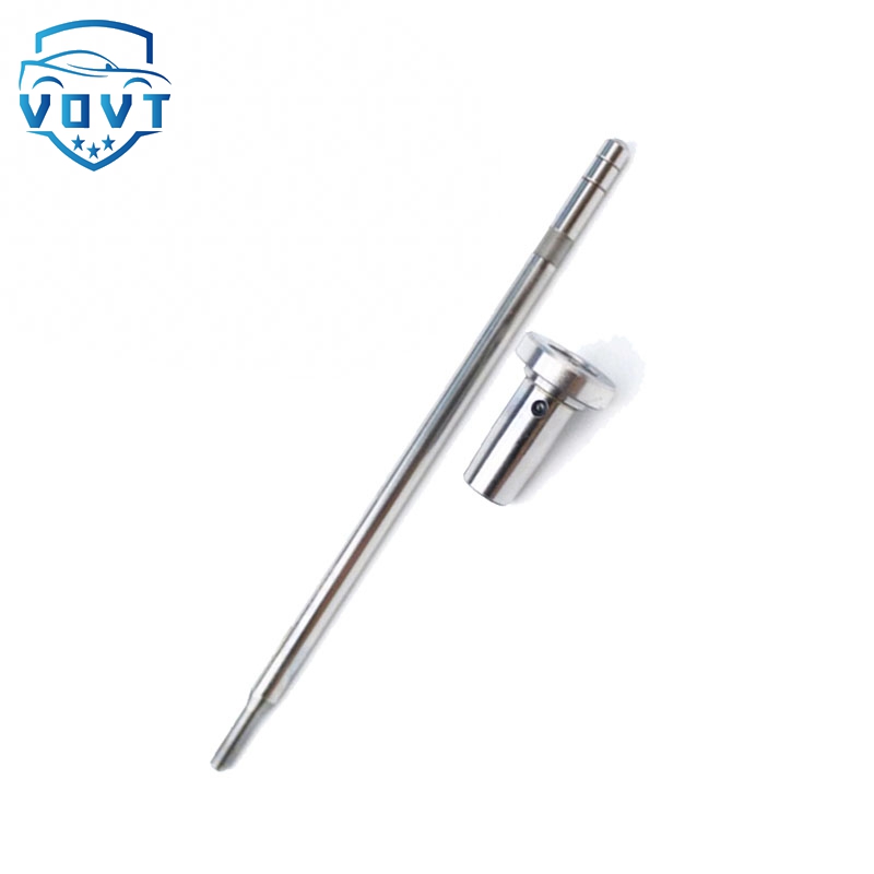
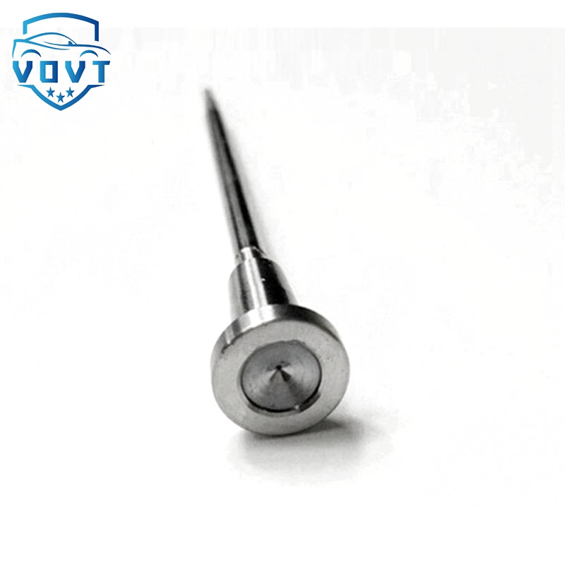
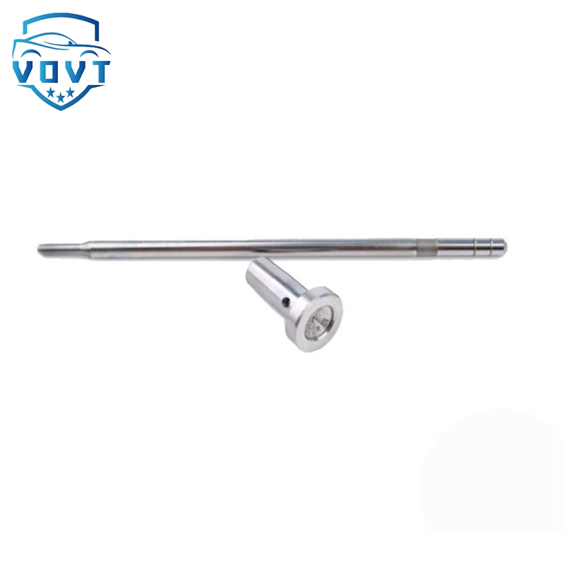
| Produce Name | F00VC01055 |
| Engine Model | / |
| Application | / |
| MOQ | 6 pcs / Negotiated |
| Packaging | White Box Packaging or Customer's Requirement |
| Lead time | 7-15 working days after confirm order |
| Payment | T/T, PAYPAL, as your preference |
Transient states analysis of CI engine injectors with the use of optical methods (PART 6)
3.5 Determination of the injection delay
The total delay time from the input signal to the beginning of the injection was defined here as the time difference between the time of the electrical signal from sequencer starting the energizing process and the time of the image with first fuel droplets occurring in the injector nozzle. The diode was used only to synchronize the results achieved from camera and from IndiModule; it reflects the resolution of one recorded frame. In this way, the calculation of fuel injection delay consists of the two main parts (equation 1): electrical and hydraulic delays. As the electric delay the authors understand the value of t-e presented in chapter 3.3 (figure 2) and it describes only the delay of the hardware. The hydraulic part (t-h, equation 2) consists of t-d described in chapter 3.3 and of t-o described in chapter 3.4. The hydraulic delay time describes mainly the injector and less the physical parameters of the fuel, such as e.g. viscosity. Equation 1 shows the total delay time according to the presented methodology:
t = t-e + t-h (1)
t-h = t-d + t-o (2)
The above equations are illustrated in figure 4, whose specific characteristics of the recorded parameters were generated in AVL Concerto. Vertical lines in the figure 4 were assigned to proper frames on the basis of the optical tests. 4. Investigation of the results for piezo- and solenoid injectors The research results were gathered into groups and presented in form of the charts. The demanded injection time was selected as constant. The results are presented in 3 groups: for short, medium and for long injection time. This type of presentation allows comparing the influence of each parameter on the fuel injection delay.
Products categories
-

High Precision New Diesel Injector Control Valv...
-

High Precision New Diesel Injector Control Valv...
-

Hot Selling New Diesel Fuel Injector Control Va...
-

Original New Common Rail Assembly F00RJ02035 fo...
-

Guaranteed Quality F00VC01520 Control Valve Val...
-

Auto parts Diesel Fuel Injector Control Valve F...


