
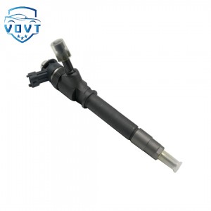
Professional Manufacture 0 445 120 036 Diesel Injector Common Rail Injector Engine Parts Vehicle Parts 0445120036


products description
| Reference. Codes | 0 445 120 036 |
| Application | / |
| MOQ | 4PCS |
| Certification | ISO9001 |
| Place of Origin | China |
| Packaging | Neutral packing |
| Quality Control | 100% tested before shipment |
| Lead time | 7~10 working days |
| Payment | T/T, L/C, Paypal, Western Union, MoneyGram or as your requirement |
CFD-Based Simulation of Cavitation Phenomena inside Injectors and Design of Cavitation Suppression Structures
1. Introduction
With the continuous increase of injection pressure in modern diesel and gasoline direct injection systems, cavitation phenomena inside injector nozzles have become increasingly prominent. Cavitation not only strongly affects internal flow characteristics and spray atomization but also accelerates material erosion, leading to performance degradation and reduced service life of injectors. Therefore, accurate prediction of cavitation behavior and effective structural suppression are of great significance for improving injector reliability and injection quality.
Computational Fluid Dynamics (CFD) provides a powerful tool for visualizing internal flow and analyzing cavitation mechanisms under complex transient conditions. In this study, a CFD-based numerical simulation method is employed to investigate the cavitation characteristics inside injector nozzles, and cavitation suppression structures are proposed and optimized based on flow field analysis.
2. Numerical Model and Simulation Method
A three-dimensional geometric model of the injector internal flow passage, including the needle seat region and nozzle holes, is established according to actual structural dimensions. The computational domain is discretized using a high-quality unstructured mesh with local refinement in the nozzle orifice and needle tip regions to ensure numerical accuracy.
The mixture multiphase model combined with the Schnerr–Sauer cavitation model is adopted to describe the phase change between liquid fuel and vapor. Turbulence effects are simulated using the realizable k–ε turbulence model. Transient simulations are conducted to capture the dynamic evolution of cavitation during the needle opening process. Boundary conditions are set according to typical operating conditions, with inlet pressure ranging from 50 MPa to 200 MPa and outlet pressure corresponding to the back-pressure environment.
3. Cavitation Characteristics Analysis
Simulation results show that cavitation mainly occurs near the inlet corner of the nozzle holes and along the wall of the orifice under high-pressure injection conditions. In the early stage of needle opening, rapid pressure drop induces the formation of incipient cavitation bubbles. As injection pressure increases, cavitation regions expand and develop into cloud cavitation, significantly disturbing the internal flow structure.
Velocity and pressure field analysis indicates that strong local pressure gradients and flow separation at sharp geometric transitions are the primary causes of cavitation generation. The vapor volume fraction increases with rising injection pressure and needle lift, resulting in unstable flow and fluctuating mass flow rate at the nozzle outlet. Excessive cavitation leads to increased hydraulic loss and irregular spray breakup behavior, which may deteriorate fuel-air mixing quality.
4. Design of Cavitation Suppression Structures
Based on the flow field characteristics obtained from CFD simulations, several cavitation suppression structures are proposed, including inlet chamfer optimization, nozzle hole rounding, and needle seat transition smoothing. By introducing a reasonable chamfer radius at the nozzle inlet, the sudden pressure drop caused by sharp corners is significantly alleviated.
Comparative simulations between the original and optimized structures demonstrate that the maximum vapor volume fraction near the nozzle inlet is reduced by more than 40% after structural optimization. The pressure distribution becomes more uniform, and the flow separation intensity is effectively weakened. In addition, the optimized structure shows a more stable mass flow curve and reduced flow pulsation, which is beneficial for improving spray consistency.
5. Results and Discussion
The influence of injection pressure and back pressure on cavitation behavior is systematically investigated. The results show that cavitation intensity increases rapidly with injection pressure but can be effectively suppressed by increasing back pressure. However, in actual engine operation, back pressure adjustment is limited; therefore, structural optimization remains the most feasible approach for cavitation control.
Furthermore, the relationship between cavitation intensity and nozzle outlet velocity is analyzed. Proper cavitation can enhance micro-scale turbulence and promote fuel atomization, while excessive cavitation causes flow choking and energy loss. The optimized structure maintains a favorable balance between atomization enhancement and erosion suppression.
The simulation results also reveal that long-term high-intensity cavitation may cause serious material erosion at the nozzle inlet. Thus, reducing cavitation not only improves injection performance but also significantly extends injector service life.
6. Conclusions
In this study, the internal cavitation behavior of an injector nozzle is investigated using a CFD-based numerical simulation approach. The formation mechanism, spatial distribution, and dynamic evolution of cavitation under high-pressure injection conditions are systematically analyzed. The results indicate that sharp geometric transitions and rapid pressure drop are the dominant factors inducing cavitation.
A series of cavitation suppression structures are proposed and verified through comparative CFD simulations. The optimized nozzle structure effectively reduces vapor volume fraction, weakens flow separation, and improves flow stability without sacrificing injection capacity. The proposed method provides a reliable theoretical basis and technical guidance for injector structural optimization and cavitation control.
This research demonstrates that CFD-based cavitation simulation combined with structural design optimization is an effective approach to improving injector performance and durability, and it has broad application prospects in high-pressure fuel injection system development.
Related products
| 1 | 5WS40200 | 11 | A2C59514909/ | 21 | 31336585 |
| 2 | FA2C53252642 | 12 | A2C59511602 | 22 | 36001726 |
| 3 | 1685796 | 13 | A2C59513556 | 23 | 1709667 |
| 4 | 31303994 | 14 | 5ws40677 | 24 | 36001727 |
| 5 | 50274V05 | 15 | 50274V0 | 25 | 9445R |
| 6 | 5WS40087 | 16 | 5WS40677 | 26 | 00Q1T |
| 7 | 16600-00Q1T | 17 | AV6Q9F593-AB | 27 | 5WS40007 |
| 8 | 00Q0H | 18 | AV6Q9F593-AA | 28 | A2C59513997 |
| 9 | 5WS40148-Z | 19 | A2C59511606 | 29 | 5WS40250 |
| 10 | 2S6Q-9F593-AB | 20 | 16600-00Q0P | 30 | A2C59514912 |
Products categories
-

Fast Delivery Diesel Fuel Injector 0445115007 0...
-

High Efficiency Common Rail Injector 0445110718...
-
Good Quality 0 445 117 083 Common Rail Diesel F...
-

High Quality New Diesel Injector 0445110414 0 4...
-

High Quality Diesel Fuel Injector 0 445 120 219...
-

Professional Manufacture 0 445 120 369 Diesel I...


