
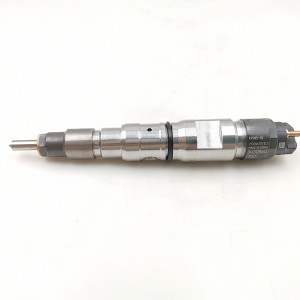
Professional Manufacture 0 445 110 081 Diesel Injector Common Rail Injector Engine Parts Vehicle Parts 0445110081


products description
| Reference. Codes | 0 445 110 081 |
| Application | / |
| MOQ | 4PCS |
| Certification | ISO9001 |
| Place of Origin | China |
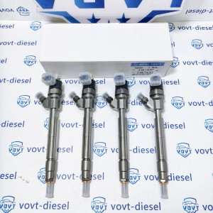
| Packaging | Neutral packing |
| Quality Control | 100% tested before shipment |
| Lead time | 7~10 working days |
| Payment | T/T, L/C, Paypal, Western Union, MoneyGram or as your requirement |
Ice-Blocking Prevention and Injection Reliability of Fuel Injectors Under Extreme Low-Temperature (−40°C) Conditions
1. Introduction
In extremely cold regions such as Northern Canada, Siberia, and high-altitude areas, diesel engines must often start and operate at temperatures as low as −40°C. Under these conditions, the fuel injector faces issues such as increased fuel viscosity, freezing of micro water droplets, needle-valve sticking, and nozzle-hole ice blockage. These problems lead to injection failure or significant deviation from calibrated injection parameters, resulting in poor cold-start performance and compromised engine reliability.
This study analyzes the ice-formation mechanisms inside injectors at extremely low temperatures and proposes engineering measures to ensure reliable fuel injection under harsh cold-start conditions.
2. Ice-Formation Mechanisms in Injectors at Low Temperatures
2.1 Freezing of Water Microdroplets Inside the Nozzle
Fuel inevitably contains trace amounts of water. When the temperature drops below 0°C, water microdroplets may:
-
Crystallize and form ice membranes around the nozzle inlet
-
Adhere to the needle-valve guide surface
-
Block nozzle holes by forming ice bridges
Result: Reduced injection quantity, deteriorated atomization, misfire, and failure to start.
2.2 Mechanical Sticking Caused by Low-Temperature Contraction
Extreme cold leads to:
-
Thickened lubrication film between the needle valve and guide
-
Reduced material clearance due to thermal contraction
-
Mismatched thermal expansion between steel and copper alloys
These result in:
-
Needle-valve sticking
-
Delayed response
-
Increased injection lag
2.3 Deterioration of Atomization Quality
At low temperatures:
-
Fuel viscosity increases dramatically
-
Spray droplets become larger
-
Spray cone angle narrows
-
Air–fuel mixing becomes insufficient
Poor atomization worsens combustion, increases white smoke, and makes cold starting more difficult.
3. Performance Degradation of Injectors at −40°C
| Parameter | Observed Behavior |
|---|---|
| Injection Quantity | Significantly reduced or completely interrupted |
| Injection Delay | Increased by 0.2–0.5 ms |
| Atomization Quality | Droplet size increases by 20–50% |
| Mechanical Issues | Needle sticking, spring weakening, nozzle blockage |
| ECU Feedback | Abnormal return-flow signals causing control errors |
4. Engineering Measures for Ice-Blocking Prevention
4.1 Structural Improvements to the Injector
(1) Hydrophobic Micro-Structured Nozzle Inlet
-
Hydrophobic coating (e.g., DLC, TiN)
-
Contact angle >120°
-
Prevents ice adhesion and crystallization
(2) Optimized Needle–Guide Clearance
-
Maintains clearance even under thermal contraction
-
Incorporates micro-lubrication grooves for cold conditions
(3) Local Thermal Management
-
Integrated micro heating film (used in some advanced injectors)
-
1–2 seconds of rapid de-icing via resistive heating
4.2 Fuel System Improvements
(1) Low-Temperature Flow Improvers
Enhance low-temperature operability by:
-
Reducing viscosity
-
Preventing wax crystal growth
-
Lowering cold filter plugging point (CFPP)
(2) Advanced Water Management
-
High-efficiency water separator
-
Real-time water-in-fuel (WIF) sensor
-
Water scavenger additives
4.3 ECU-Based Compensation Strategies at −40°C
(1) Preheating Injection (Pilot Heating Injection)
A very small pre-injection is used to:
-
Warm the nozzle tip
-
Increase fuel temperature locally
-
Reduce ice-blocking tendency
(2) Increased Drive Current
To overcome additional resistance caused by ice and thickened fuel film.
(3) Adaptive Rail-Pressure Control
-
Higher pressure → improves atomization
-
Lower pressure → reduces injector mechanical load when ice-blocking is suspected
ECU uses real-time signals to switch modes intelligently.
(4) Injector Self-Diagnosis and De-Icing Mode
ECU detects abnormalities in return flow and activates:
-
High-frequency needle vibration
-
Intermittent heating (if heating element exists)
-
Controlled pressure pulsing
5. Reliability Verification Methods
5.1 Low-Temperature Chamber Testing
Simulated tests at −20°C / −30°C / −40°C:
-
Repeated cold starts
-
Rail-pressure response evaluation
-
Spray imaging and injection waveform analysis
5.2 Ice-Blocking Sensitivity Testing
Fuel is conditioned with controlled water content (50–200 ppm) to evaluate freezing effects.
5.3 Needle-Valve Dynamics Testing
Using laser displacement sensors and high-speed imaging to measure:
-
Needle response delay
-
Sticking probability
-
Motion attenuation at low temperatures
6. Conclusion
At −40°C, injectors suffer from ice formation, increased viscosity, and mechanical contraction effects. These issues cause injection-quantity deficits, delayed response, and poor atomization. Through structural anti-icing design, fuel-treatment methods, and intelligent ECU compensation, the injection reliability under extreme cold-start conditions can be significantly improved. This provides strong technical support for diesel engines operating in severe winter environments.
Related products
| 1 | 5WS40200 | 11 | A2C59514909/ | 21 | 31336585 |
| 2 | FA2C53252642 | 12 | A2C59511602 | 22 | 36001726 |
| 3 | 1685796 | 13 | A2C59513556 | 23 | 1709667 |
| 4 | 31303994 | 14 | 5ws40677 | 24 | 36001727 |
| 5 | 50274V05 | 15 | 50274V0 | 25 | 9445R |
| 6 | 5WS40087 | 16 | 5WS40677 | 26 | 00Q1T |
| 7 | 16600-00Q1T | 17 | AV6Q9F593-AB | 27 | 5WS40007 |
| 8 | 00Q0H | 18 | AV6Q9F593-AA | 28 | A2C59513997 |
| 9 | 5WS40148-Z | 19 | A2C59511606 | 29 | 5WS40250 |
| 10 | 2S6Q-9F593-AB | 20 | 16600-00Q0P | 30 | A2C59514912 |
Products categories
-
Diesel Injector Fuel Injector 0445120443 compat...
-

High Quality Diesel Injector 0445110418 0 445 1...
-
Professional Manufacture 0 445 110 317 Diesel I...
-

Professional Manufacture 0 445 120 387 Diesel ...
-

Professional Manufacture 0 445 120 369 Diesel I...
-

Made in China Common Rail Injector Fuel Injecto...


