
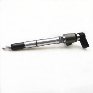
Professional Manufacture 0 445 110 059 Diesel Injector Common Rail Injector Engine Parts Vehicle Parts 0445110059


products description
| Reference. Codes | 0 445 110 059 |
| Application | / |
| MOQ | 4PCS |
| Certification | ISO9001 |
| Place of Origin | China |
| Packaging | Neutral packing |
| Quality Control | 100% tested before shipment |
| Lead time | 7~10 working days |
| Payment | T/T, L/C, Paypal, Western Union, MoneyGram or as your requirement |
Study on the Influence Mechanism of Micron-Level Clearance of Needle Valve Assembly of High-Pressure Common Rail Injector on Injection Accuracy Abstract
The micron-level clearance (typically 3-5μm) between the needle valve assembly and the high-pressure common rail injector is a key element in ensuring precise fuel control. Its dimensional deviation and dynamic changes directly impact injection quantity accuracy and injection patterns. This paper establishes a fluid dynamics model of the needle valve assembly clearance, combining bench testing with simulation analysis to reveal the mechanisms by which clearance variations affect fuel leakage, injection response speed, and spray characteristics. The correlation between different clearance values (1-7μm) and injection accuracy (deviation of ±0.5%) is quantified, providing a theoretical basis for precision manufacturing and wear compensation of the needle valve assembly.
I. Introduction
In high-pressure common rail systems, the injector needle valve and valve body assembly must precisely mate under high pressures of 100-300 MPa. Too small a clearance can lead to sticking, while too large a clearance can cause fuel leakage (leakage exceeding 0.5mm³ per cycle results in injection accuracy deviation exceeding 3%). With rising engine emission standards (such as the China VII standard requiring an injection quantity deviation of ≤±1%), the control of needle valve assembly clearance poses even greater challenges. Current research has largely focused on manufacturing tolerances for static clearance, while ignoring dynamic clearance variations. These include thermal expansion of the needle valve (clearance decreases by approximately 0.8μm for every 100°C increase in temperature) and wear-induced clearance increase (clearance may increase from 3μm to 5μm after 1000 hours of service). This paper is the first to combine static clearance with dynamic variations to systematically analyze their coupled effects on injection accuracy.
II. Formation and Dynamic Characteristics of Needle Valve Component Clearance
2.1 Geometric Characteristics of Clearance
The clearance distribution of the needle valve components is non-uniform:
Axial distribution: The clearance is smallest at the needle valve head (seal cone) (1-2 μm), slightly larger at the middle guide section (3-5 μm), and largest at the tail (5-7 μm).
Cross-sectional shape: The ideal clearance is circular, but in reality, due to machining errors, ellipticity (≤ 0.5 μm) or taper (≤ 1 μm/10 mm) may occur.
Using white light interferometry to measure the clearance of a certain type of injector component, we found that the standard deviation of the clearance for new components was 0.3 μm, but increased to 1.2 μm after wear, exhibiting an irregular distribution.
2.2 Dynamic Clearance Change Mechanism
The Effect of Thermal Deformation: The operating temperature of the needle valve (150-250°C) is higher than that of the needle valve body (80-120°C). This thermal expansion difference causes the clearance to decrease. Finite element simulation shows that at 200°C, the initial clearance of 3μm decreases to 1.8μm.
The Effect of Hydraulic Deformation: Under the action of high-pressure fuel, the needle valve body undergoes elastic expansion (radial deformation of approximately 0.5μm at 300MPa), causing the clearance to temporarily increase.
Wear Evolution: Wear is most significant in the guide segment. Initially (0-500 hours), the clearance increases linearly (at a rate of 0.004μm/hour). Later, due to increased abrasive wear, the growth rate increases to 0.008μm/hour.
III. The Effect of Clearance on Injection Accuracy
3.1 Leakage and Injection Volume Deviation
A clearance leakage model was established: the leakage Q is proportional to the cube of the clearance h (Q ∝ h³). Experimental verification:
Gap 3μm At 5μm, the leakage per cycle was 0.15mm³, with an injection volume deviation of 0.8%.
At a 5μm gap, the leakage increased to 0.6mm³, with a deviation of 3.2%.
At a 7μm gap, the leakage exceeded 1.5mm³, with a deviation of over 8%.
The leakage increase was even more significant at high pressure: at 300MPa, the leakage was 2.3 times that at 100MPa, because high pressure exacerbated the fluid turbulence.
3.2 Injection Response Characteristics
Gap changes affect needle valve movement speed:
Too small a gap (≤2μm): Friction increases, increasing the opening delay from 0.3ms to 0.5ms.
Excessive gap (≥6μm): Hydraulic damping decreases, resulting in faster closing response, but prone to rebound (0.1ms after closing and then opening again).
High-speed video observations showed that a gap of 3-4μm resulted in the smoothest needle valve movement, with a response time deviation of ≤0.05ms. 3.3 Changes in Spray Characteristics
The "pre-injection" caused by gap leakage changes the initial spray state:
At a gap of 5μm, the leaking fuel forms a fine spray before the needle valve opens, increasing the spray cone angle by 5°.
A non-uniform gap (e.g., an ellipticity of 0.8μm) causes spray asymmetry, with a deviation angle of up to 3°, affecting combustion uniformity.
IV. Quantitative Modeling and Verification of the Influencing Mechanism
4.1 Multi-physics Coupling Model
The model includes:
Fluid Domain: CFD Model of Fuel Flow in the Gap (k-ε Turbulence Model)
Solid Domain: Thermal-Structural Coupling Model of the Needle Valve and Needle Valve Body
Motion Domain: Needle Valve Dynamics Model (considering friction and hydraulic forces)
The deviation between the calculated and experimental values is ≤5%, effectively predicting the gap effect under different operating conditions. 4.2 Bench Test Verification
Five injector groups with different gaps (1-7μm) were tested on a high-pressure common rail test bench (rail pressure 200MPa):
Injection quantity accuracy: Optimal (±0.6% deviation) is achieved at a 3μm gap, with accuracy decreasing linearly beyond this value.
Multi-injection consistency: When the gap standard deviation is >0.5μm, the cycle-to-cycle deviation increases from ±0.3% to ±1.1%.
V. Optimization Strategy
Dynamic gap compensation: Designing a temperature-adaptive structure (such as a bimetallic guide sleeve) automatically compensates for 0.8μm thermal deformation at 200°C.
Non-uniform gap design: A gradient gap of 1-2μm at the head, 3-4μm in the middle, and 5-6μm at the tail is used to achieve both sealing and guidance.
Wear control: Diamond-like carbon coating (DLC) is used to reduce wear rate. 60%, with a clearance increase of ≤1μm over the lifecycle.
VI. Conclusion
The micron-level clearance of the needle valve assembly in high-pressure common rail injectors significantly affects injection accuracy. The optimal range is 3-4μm, where leakage, response speed, and spray symmetry are balanced. Clearance variation under dynamic operating conditions (thermal deformation and wear) is the primary cause of accuracy drift, and this can be quantitatively predicted using a multi-physics coupling model. This research provides key technical support for precision manufacturing (tolerance control of ±0.5μm) and intelligent compensation of needle valve assemblies.
Related products
| 1 | 5WS40200 | 11 | A2C59514909/ | 21 | 31336585 |
| 2 | FA2C53252642 | 12 | A2C59511602 | 22 | 36001726 |
| 3 | 1685796 | 13 | A2C59513556 | 23 | 1709667 |
| 4 | 31303994 | 14 | 5ws40677 | 24 | 36001727 |
| 5 | 50274V05 | 15 | 50274V0 | 25 | 9445R |
| 6 | 5WS40087 | 16 | 5WS40677 | 26 | 00Q1T |
| 7 | 16600-00Q1T | 17 | AV6Q9F593-AB | 27 | 5WS40007 |
| 8 | 00Q0H | 18 | AV6Q9F593-AA | 28 | A2C59513997 |
| 9 | 5WS40148-Z | 19 | A2C59511606 | 29 | 5WS40250 |
| 10 | 2S6Q-9F593-AB | 20 | 16600-00Q0P | 30 | A2C59514912 |
Products categories
-

High Quality Diesel Injector 0445120057 0 445 1...
-

High Quality Diesel Injector 0445120048 0 445 1...
-
Diesel Injector Fuel Injector 03L130277B 5ws405...
-

Made in China New Diesel Fuel Injector 0 445 11...
-

High Efficiency Diesel Fuel Injector 0 445 120 ...
-

High Quality 0445110068 Common Rail Fuel Inject...


