
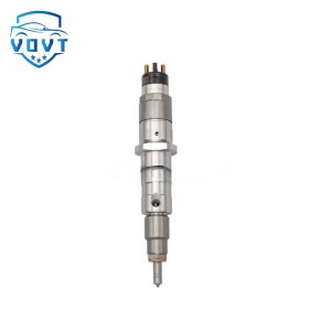
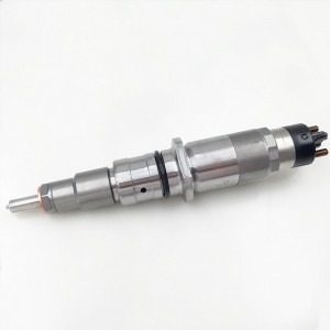
Made in China Good Quality KBAL65S43 Diesel Fuel Injector Common Rail Injector Engine Parts


products description
| Reference. Codes | KBAL65S43 |
| Application | / |
| MOQ | 4PCS |
| Certification | ISO9001 |
| Place of Origin | China |
| Packaging | Neutral packing |
| Quality Control | 100% tested before shipment |
| Lead time | 7~10 working days |
| Payment | T/T, L/C, Paypal, Western Union, MoneyGram or as your requirement |
How does a fuel injector work?
Core structure and working basis
1. Electromagnetic drive assembly
Electromagnetic coil: generates magnetic field when powered on, attracting armature; magnetic field disappears when powered off, and armature returns to its original position under the action of reset spring.
Armature and valve needle: armature and valve needle are rigidly connected, and the armature moves to drive the valve needle to open or close the spray hole.
2. Fuel passage and sealing structure
Oil inlet: connected to fuel rail (high-pressure oil circuit) or fuel pipe (low-pressure oil circuit).
Valve seat and spray hole: the conical surface of valve needle and valve seat cooperates to form a sealing surface, and the spray hole diameter is usually 0.1-0.3mm (direct injection in cylinder) or 0.5-1mm (manifold injection).
Workflow: The whole process from electrical signal to fuel injection
1. Power-on stage (taking electromagnetic fuel injector as an example)
ECU sends out fuel injection signal: After the engine control unit (ECU) calculates the fuel injection demand according to the working conditions (such as speed, load, temperature), it sends a pulse voltage signal (usually 12V or 24V) to the injector electromagnetic coil.
Electromagnetic force overcomes spring force: The coil is energized to generate a magnetic field, which attracts the armature to drive the valve needle upward, open the valve seat, and high-pressure fuel is sprayed out through the spray hole.
Opening response time: The time from power-on to the full opening of the valve needle is called "opening delay", which is usually 0.5-1.5ms (depending on the coil inductance and armature quality).
2. Fuel injection duration stage
The amount of fuel injection is determined by the power-on time: ECU accurately adjusts the amount of fuel injection by controlling the pulse width (i.e., the power-on time). For example:
When idling, the power-on time is about 1-2ms, and the injection volume is 5-10mg/cycle;
When full load, the power-on time can reach 5-10ms, and the injection volume increases to 30-50mg/cycle.
Fuel atomization principle: When high-pressure fuel (such as direct injection 20-350bar) passes through the spray hole, it produces cavitation effect due to high-speed flow (flow velocity can reach 100-300m/s), breaking into 10-50 micron oil droplets, which mix with air to form a combustible mixture.
3. Power-off shutdown stage
Magnetic field disappearance and reset: ECU cuts off the coil current, the magnetic field decays, the reset spring pushes the armature to drive the valve needle down, the valve needle and the valve seat fit tightly, and the fuel injection stops.
Closing response time: The time from power off to complete sealing is called "closing delay", which is usually 0.3-0.8ms. It is necessary to ensure that there is no fuel dripping (such as the direct injection system in the cylinder requires the sealing pressure to be maintained at 50-100bar after shutdown).
Key working parameters and control logic
1. Injection timing (injection time)
Precise control based on crankshaft position: ECU determines piston position and valve status according to the signals of crankshaft position sensor (CKP) and camshaft position sensor (CMP), and triggers injection at the best time:
Manifold injection: Usually injects fuel during the intake stroke (10-30° crankshaft angle before the intake valve opens), so that the fuel has sufficient time to mix with the air;
Direct injection: According to the combustion mode (such as homogeneous combustion, stratified combustion), the injection time is precisely controlled during the compression stroke (such as 60-10° before compression top dead center).
2. Fuel pressure and injection pressure difference
Injection pressure difference = fuel rail pressure - ambient pressure:
Manifold injection system: fuel rail pressure 0.2-0.35MPa, manifold negative pressure about -0.03MPa, pressure difference 0.23-0.38MPa;
Direct injection system: fuel rail pressure 2-35MPa (high pressure mode can reach 350bar), combustion chamber pressure in compression stroke can reach 0.6-1.2MPa, pressure difference 1.4-34.4MPa (high pressure difference ensures that fuel penetrates air resistance and reaches the vicinity of the spark plug).
3. Duty cycle and injection frequency
Duty cycle: the proportion of power-on time to cycle, for example, the duty cycle is about 10%-20% at idle speed and can reach 50%-80% at full load;
Injection frequency: related to engine speed. When the four-cylinder engine is 3000rpm, each injector needs to inject 25 times per second (i.e., frequency 25Hz), and the electromagnetic coil needs to have high-frequency response capability (response frequency ≥50Hz).
Differences in the working principles of different types of injectors
Type Structural features Core differences in working principles Typical pressures and application scenarios
Manifold injection injector Single or double holes, longer valve needle stroke (0.5-1mm) Relying on the fuel pressure and the manifold negative pressure difference for injection, atomization depends on the secondary breakage of the intake airflow 0.2-0.35MPa, used in economical passenger cars
Direct injection injector Multi-hole design (6-12 holes), short valve needle stroke (0.1-0.3mm), with pressure compensation structure High-pressure fuel is directly atomized in the combustion chamber, and it is necessary to resist high-temperature carbon deposition. The injection angle precisely matches the piston pit 2-35MPa (high-pressure common rail), used in turbocharged engines
Piezoelectric injector Piezoelectric crystal replaces electromagnetic coil, with faster response speed (opening delay < 0.1ms) Piezoelectric effect produces deformation to push the valve needle, which can realize multiple injections (such as pre-injection + main injection + post-injection) 100-350MPa, used in high-end diesel / Gasoline direct injection engine
Mechanical injector (diesel) The camshaft drives the plunger pump oil, and the injection pressure valve opens the spray hole. The injection pressure changes with the engine load, relies on mechanical adjustment, and has low precision 10-200MPa (traditional diesel engine), which is gradually replaced by electronic control injectors
The relationship between working principle and engine performance
1. The impact of injection atomization quality on combustion
Poor atomization: When the oil droplet diameter is > 50 microns, it is easy to cause incomplete combustion, increased carbon deposits, and an increase in fuel consumption of 10%-20%;
Optimized design: The direct injection injector in the cylinder controls the oil droplet diameter to 10-20 microns through multi-hole injection (such as 8 holes) and high pressure (200bar+), achieving stratified combustion and improving thermal efficiency.
2. The impact of injection timing on emissions
Premature injection: fuel wets the cylinder wall (attaches to the cylinder wall), resulting in increased HC emissions;
Late injection: incomplete combustion, increased CO and soot (PM) emissions, and the OBD system may report a "misfire" fault code.
VI. Association between fault cases and principles
Aging of the electromagnetic coil: increased inductance, longer opening delay, delayed injection timing, and weak engine acceleration;
Valve needle stuck: the valve needle cannot be completely closed due to fuel impurities or carbon deposits, fuel leaks, causing idle jitter and soaring fuel consumption;
Nozzle hole blockage: impurities (such as colloid, metal debris) block the spray hole, the amount of fuel injection is reduced and the atomization is uneven, a single cylinder works poorly, and a "missing cylinder" phenomenon occurs.
Related products
| 1 | 5WS40200 | 11 | A2C59514909/ | 21 | 31336585 |
| 2 | FA2C53252642 | 12 | A2C59511602 | 22 | 36001726 |
| 3 | 1685796 | 13 | A2C59513556 | 23 | 1709667 |
| 4 | 31303994 | 14 | 5ws40677 | 24 | 36001727 |
| 5 | 50274V05 | 15 | 50274V0 | 25 | 9445R |
| 6 | 5WS40087 | 16 | 5WS40677 | 26 | 00Q1T |
| 7 | 16600-00Q1T | 17 | AV6Q9F593-AB | 27 | 5WS40007 |
| 8 | 00Q0H | 18 | AV6Q9F593-AA | 28 | A2C59513997 |
| 9 | 5WS40148-Z | 19 | A2C59511606 | 29 | 5WS40250 |
| 10 | 2S6Q-9F593-AB | 20 | 16600-00Q0P | 30 | A2C59514912 |
Products categories
-
Diesel Fuel Injector 0445120035 Bosch for Cummi...
-

New High Quality Diesel Injector 250-1313 10R-9...
-

High Quality Diesel Injector 4026222 Diesel Fue...
-
Diesel Injector Fuel Injector 0445120328 Bosch ...
-

New High Quality Diesel Injector 294-3027 294-3...
-

New High Quality Diesel Injector 573-4231 573-4...


