
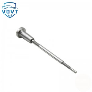
High Precision New Diesel Injector Control Valve F00ZC01309 Valve Assembly for Fuel Injector Engine Spare Parts


Products Description
| Reference Codes | F00ZC01309 |
| Application | / |
| MOQ | 6 PCS |
| Certification | ISO9001 |
| Place of Origin | China |
| Packaging | Neutral packing |
| Quality Control | 100% tested before shipment |
| Lead time | 7~10 working days |
| Payment | T/T, L/C, Paypal, Western Union, MoneyGram or as your requirement |
How to check the injector valve assembly
Appearance and structural inspection (preliminary screening)
External cleaning and visual inspection
Use compressed air or cleaning agent to remove carbon deposits and oil stains on the outside of the injector, focusing on the following observations:
Sealing parts: whether the O-ring is aged (cracked, deformed), whether the copper pad is damaged, which may cause fuel leakage or air intake.
Wiring plug: whether the pins are oxidized, bent, and whether the insulation layer is damaged (may cause abnormal signal transmission).
Valve body surface: whether there are cracks (especially the ceramic parts of piezoelectric injectors), or discoloration caused by overheating (such as blue ablation marks).
Valve core and valve seat coordination inspection
Disassemble the injector (professional tools are required) and remove the valve assembly (needle valve pair):
Manual activity test: gently push the valve core, it should be able to move smoothly in the valve seat without sticking, and the valve core should be able to automatically reset after releasing the hand (by spring force). If stuck, it may be stuck due to carbon deposits, wear or impurities.
Sealing surface observation: Use a magnifying glass to check the sealing cone surface of the valve core and the valve seat. If there are scratches, pits or carbon deposits, it will cause loose sealing, dripping or poor atomization.
Sealing test (key performance verification)
Static pressure retention test
Tools: injector test bench or manual pressure pump (such as Bosch FSA740).
Steps:
Install the injector to the test bench and pass the rated pressure (such as 5-10MPa for gasoline engines and 100-200MPa for diesel engines).
After shutting off the fuel supply, observe the pressure drop rate:
Under normal circumstances, the pressure drop within 10 seconds should be less than 5% (such as from 100MPa to below 95MPa is abnormal).
If the pressure drops rapidly, it means that the valve core and the valve seat are not sealed well, and the needle valve pair needs to be replaced.
Dynamic leakage test
Simulate the engine working condition on the test bench and drive the injector to open/close with high frequency (such as 50Hz):
Observe the oil return volume: The oil return volume of a single cylinder at idle speed should be less than 5mL/min (refer to the vehicle model manual for details). Excessive oil return may be caused by wear of the valve assembly or seal failure.
Check whether there is fuel dripping at the spray hole (after the injector is closed). If there is dripping, it means that the valve core is closed late or the seal is not tight.
Electrical performance test (for electronically controlled injectors)
Coil resistance measurement
Disconnect the injector plug and use a multimeter to measure the resistance of the solenoid valve or piezoelectric crystal:
Electromagnetic injector: low resistance type (2-3Ω) is suitable for peak hold drive circuit, and high resistance type (12-15Ω) is suitable for direct drive circuit. If the resistance is ∞ or <1Ω, it means that the coil is open or short-circuited.
Piezoelectric injector: The resistance is usually >1MΩ (high insulation requirements). If the resistance value is low, the internal piezoelectric crystal may be damaged.
Drive signal waveform analysis (advanced detection)
Tools: Oscilloscope or special diagnostic instrument (such as Launch X-431).
Steps:
Start the engine and read the injector drive signal waveform.
The normal waveform should be a regular square wave with steep rising/falling edges (<0.5ms) and pulse width that varies with the working conditions (such as 2-3ms at idle and 5-10ms at acceleration).
If the waveform is distorted, the amplitude decreases or the pulse width is abnormal, it indicates a drive circuit failure (such as abnormal ECU output or wiring harness interference).
Spray shape and flow test
Spray shape observation
Drive the injector at rated pressure on the test bench and observe the spray shape:
Normal shape: conical uniform spray beam with clear edges, no oil droplets or deflection.
Abnormal shape:
Oil drop shape → insufficient injection pressure or blocked spray hole;
Deflection → asymmetry caused by wear or carbon deposition of spray hole;
Columnar flow → valve core stuck or sealing surface damaged.
Flow consistency test
Comparative test of the injectors of multi-cylinder engines:
Drive the injectors of each cylinder with the same pulse width (such as 5ms), collect the sprayed fuel and weigh it.
The difference in the injection amount of each cylinder should be less than 3%, otherwise the injector needs to be cleaned or replaced.
Dynamic response test
Measure the delay time from the opening of the injector to the stable injection (normally <0.3ms), and the residual injection amount after closing (should be <0.1mm³), and evaluate the dynamic performance of the valve assembly.
Endoscopic inspection (internal carbon deposition evaluation)
Tool: industrial endoscope (diameter <3mm).
Steps:
Insert the endoscope into the injector spray hole and observe the internal carbon deposition.
If the spray hole is covered by carbon deposition >50%, or there is obvious coking on the needle valve surface, ultrasonic cleaning or chemical immersion (such as special injector cleaning agent) is required.
Verification of engine matching (vehicle installation test)
Data flow analysis
Use the diagnostic instrument to read the engine operation data, focusing on:
Deviation between the actual rail pressure and the target rail pressure (normal <±5MPa). If the deviation is too large, the injector may leak or the valve assembly may respond late.
Difference in the injection pulse width of each cylinder (if a cylinder is more than 10% larger than the average value, the injector flow of the cylinder may be abnormal).
Cylinder disconnection test
Disconnect the injectors of each cylinder in turn at idle speed and observe the speed change:
Under normal circumstances, the speed should drop by 50-100rpm after disconnecting a cylinder;
If the speed does not change or rises instead, it means that the injector of the cylinder is not working properly (the valve assembly may be stuck or not closed tightly).
Fault case analysis
Case 1: A diesel vehicle is underpowered and has serious black smoke.
Detection: The injector spray is columnar, and the seal test pressure drops too fast.
Cause: The sealing cone of the valve assembly is scratched by metal debris, and it is normal after replacing the needle valve pair.
Case 2: A gasoline engine has difficulty in cold starting and jitters at idle speed.
Detection: The resistance of the injector coil is normal, but the waveform shows a closing delay of 0.5ms (standard <0.2ms).
Cause: The valve core is stuck due to carbon deposits. The fault is eliminated after cleaning.
Precautions
Cleaning operation: Disassembly and assembly of the injector must be carried out in a dust-free environment to prevent impurities from entering the precision parts.
Special tools: Use tools recommended by the manufacturer (such as torque wrenches, special sockets) to avoid damage to components.
Calibration requirements: After replacing the valve assembly or injector, the injection timing and injection amount must be recalibrated (some models need to be programmed through the diagnostic instrument).
Products categories
-

High Precision New Diesel Injector Control Valv...
-

High Precision New Diesel Injector Control Valv...
-

Original Common Rail Injector Control Valve Ass...
-

High Quality New Diesel Injector Control Valve ...
-

Common Rail Fuel Injector Control Valve Assembl...
-
High Quality Common Rail Control Valve Set Asse...


