
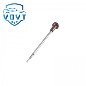
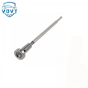
High Precision New Diesel Injector Control Valve F00RJ01895 Valve Assembly for Fuel Injector Engine Spare Parts


Products Description
| Reference Codes | F00RJ01895 |
| Application | / |
| MOQ | 6 PCS |
| Certification | ISO9001 |
| Place of Origin | China |
| Packaging | Neutral packing |
| Quality Control | 100% tested before shipment |
| Lead time | 7~10 working days |
| Payment | T/T, L/C, Paypal, Western Union, MoneyGram or as your requirement |
Research on pressure loss and flow characteristics of valve components based on CFD
Abstract
Valve assemblies are crucial components in hydraulic and fuel injection systems. Their pressure loss and flow characteristics directly determine the system's energy utilization and operational stability. This paper uses computational fluid dynamics (CFD) to numerically simulate the flow characteristics of valve assemblies under different operating conditions. Combined with theoretical analysis, the pressure loss mechanism and flow patterns are explored, providing a reference for optimizing valve assembly structure.
1 Introduction
During valve assembly operation, fluid must pass through the valve orifice, throttle gap, and internal flow passages, inevitably generating energy losses. Excessive pressure loss not only reduces system efficiency but can also cause noise, vibration, and localized cavitation. Therefore, accurately predicting and optimizing the flow and pressure characteristics of valve assemblies is crucial for improving the performance of hydraulic and fuel systems.
2 Numerical Simulation Method
This paper uses CFD software to perform three-dimensional modeling and flow field analysis of a typical valve assembly. Boundary conditions are set as constant inlet pressure, constant outlet pressure, or mass flow control, and hydraulic oil is the fluid medium. The RNG k-ε turbulence model was used to simulate complex turbulent structures. A combination of steady-state and transient calculations was used to analyze the flow conditions at different openings. Simulation results include velocity vector distribution, pressure contours, and local energy loss.
3. Pressure Loss Characteristic Analysis
Simulation results show that the valve orifice constriction area is the primary source of energy loss. As the valve core opening increases, the local constriction effect weakens, and pressure loss decreases. At small and medium openings, the high-speed fluid jet forms significant vortices, which enhance local turbulent dissipation and, consequently, increase the proportion of pressure loss. Furthermore, valve seat geometry significantly affects pressure loss. Appropriately increasing chamfers or optimizing transition surfaces can reduce fluid separation and local vortices.
4. Flow Characteristics Study
The flow characteristics of valve assemblies are typically characterized by the flow coefficient or flow-pressure differential curve. CFD results show that flow increases nonlinearly with increasing differential pressure and gradually approaches saturation. Flow deviation is significant at small openings, primarily due to local flow resistance and fluid attachment effects. When the valve is fully open, the flow rate approaches the theoretical value, but some deviation still exists, indicating that turbulent dissipation and localized cavitation cannot be ignored. Comparing the results with different structural parameters reveals that valve core radius and symmetry contribute to improved flow uniformity and stability.
5 Conclusion
The CFD-based analysis method accurately reveals the pressure loss mechanism and flow characteristics of the valve assembly. The study demonstrates that appropriate geometric optimization can effectively reduce energy loss and improve flow characteristics, thereby increasing system efficiency. Future research could further incorporate multiphase flow models to consider the coupled effects of cavitation and temperature on valve assembly performance.
Products categories
-

Piezoelectric Valve Genuine Common Rail Fuel In...
-

High Precision New Diesel Injector Control Valv...
-

Original Common Rail Injector Control Valve Ass...
-

High Quality Common Rail Control Valve Set Asse...
-
Genuine New Common Rail Valve Assembly F00VC013...
-
New Diesel Injector Valve F00RJ01819 for Fuel I...


