
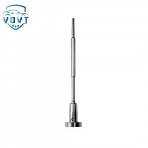
High Precision New Diesel Injector Control Valve F00RJ01218 Valve Assembly for Fuel Injector Engine Spare Parts


Products Description
| Reference Codes | F00RJ01218 |
| Application | / |
| MOQ | 6 PCS |
| Certification | ISO9001 |
| Place of Origin | China |
| Packaging | Neutral packing |
| Quality Control | 100% tested before shipment |
| Lead time | 7~10 working days |
| Payment | T/T, L/C, Paypal, Western Union, MoneyGram or as your requirement |
Injector valve assembly: structure, principle, performance and optimization
The injector valve assembly plays a central role in the engine's fuel injection system, with its performance directly impacting the engine's power output, fuel economy, and emissions. A deeper understanding of the injector valve assembly is crucial for advancing engine technology.
I. Exploring the Structure
The injector valve assembly is a complex and intricate structure, primarily comprising a needle valve, needle valve body, spring, armature, and solenoid coil. The needle valve and needle valve body form a high-precision mating pair, with a clearance measured in microns, typically 3-5μm. This precise fit is crucial for precisely controlling the opening and closing of fuel injection. The spring provides a stable closing force for the needle valve, ensuring it remains tightly against the valve body during non-injection periods, effectively preventing fuel leakage. The armature and solenoid coil work together. When the solenoid coil is energized, a strong magnetic field is generated, attracting the armature, which forces the needle valve upward, overcoming the spring force and opening the injection port, allowing fuel to be ejected.
II. Analyzing the Working Principle
The operating process of the injector valve assembly can be broken down into three phases: opening, injection, and closing. During the on-stage phase, the engine control unit (ECU) issues an injection command, instantly flowing current into the solenoid coil. The powerful electromagnetic force rapidly attracts the armature, which drives the needle valve upward, opening the spray hole and beginning the injection of high-pressure fuel. During the injection phase, fuel is continuously and steadily sprayed under high pressure. Injection parameters, such as injection volume and injection rate, are determined by the injector valve assembly structure and the ECU control strategy. During the off-stage phase, the ECU stops supplying power to the solenoid coil, instantly dissipating the magnetic field. The needle valve, acting under spring force, quickly retracts, closing the spray hole and terminating fuel injection. The entire process is seamless.
III. Key Technical Indicators
3.1 Injection Accuracy
Injection accuracy encompasses both injection volume and injection timing. Injection accuracy is affected by numerous factors, including the clearance between the needle valve and the needle valve body, nozzle hole dimensional accuracy, fuel pressure stability, and solenoid control accuracy. Excessive clearance can lead to fuel leakage, causing the actual injection volume to fall below the set value. Deviations in nozzle hole dimensional accuracy can alter the fuel flow area, further affecting injection volume. Relevant research shows that a nozzle diameter deviation of ±0.01mm can result in a fuel injection quantity deviation of up to ±5%. In high-pressure common rail systems, high-precision machining and advanced pressure control technology enable fuel injection quantity accuracy to within ±1%. Injection timing accuracy primarily depends on the solenoid response speed, needle valve motion characteristics, and ECU control accuracy. Using a fast-response solenoid, optimizing the needle valve structure, and combining precise ECU control algorithms can achieve injection timing accuracy of ±0.5° C.A. (crankshaft angle).
3.2 Atomization Performance
Atomization performance is primarily measured by atomized particle size and spray cone angle. The nozzle structure and size significantly influence the atomized fuel particle size. A smaller nozzle diameter allows the fuel to be more easily broken into smaller droplets under high pressure, but excessively small nozzles are prone to clogging. For example, micro-hole (0.1-0.2mm diameter) fuel injectors can achieve an average fuel atomization particle size of 10-20μm, significantly improving atomization compared to traditional nozzles (0.2-0.4mm diameter). Furthermore, increasing injection pressure can also help reduce atomized particle size. In a high-pressure common rail system, increasing injection pressure from 100MPa to 200MPa can reduce atomized particle size by approximately 30%. The spray cone angle is determined by the needle valve head shape and nozzle arrangement. A suitable spray cone angle ensures uniform fuel distribution within the combustion chamber and thorough mixing with air. In direct injection engines, the spray cone angle typically ranges from 60° to 120°, with the specific value optimized based on the combustion chamber geometry and air flow characteristics.
3.3 Durability and Reliability
Injector valve assemblies operate in harsh environments, exposed to high temperatures, high pressures, and high speeds for extended periods, placing extremely high demands on their durability and reliability. In terms of material selection, needle valves and needle valve bodies are often made of high-hardness, highly wear-resistant alloys, such as tungsten- and molybdenum-containing alloy steels. Through quenching, tempering, and surface nitriding, surface hardness can reach HV900-1200, effectively improving wear resistance. When operating in high-temperature environments, thermal stability is also a consideration. Key components are manufactured from high-temperature alloys capable of withstanding temperatures of 300-500°C. Furthermore, impurities, moisture, and acidic substances in the fuel's combustion products can cause wear and corrosion in the injector valve assembly. Optimizing fuel filter accuracy, reducing impurity ingress, and adding anti-corrosion additives to the fuel can effectively reduce wear and corrosion, extending its service life. Surface coatings such as chrome plating and nickel-phosphorus alloy plating can also improve surface hardness and corrosion resistance.
IV. Performance Optimization Strategies
4.1 Structural Parameter Optimization
Utilizing multi-physics coupled simulation software, including CFD (computational fluid dynamics), EM (electromagnetism), and structural mechanics, we simulated the fuel flow, electromagnetic force, and structural deformation of the injector valve assembly during operation. Simulations analyzed various structural parameters, such as nozzle diameter, needle lift, and number of solenoid coil turns, to establish a parameter-performance relationship model. For example, simulations revealed that reducing the nozzle diameter within a certain range significantly improved fuel atomization, but this increased fuel flow resistance, necessitating comprehensive consideration of factors such as injection pressure for optimization. Using the response surface methodology, we constructed a response surface model using key performance indicators of the injector valve assembly, such as injection quantity accuracy, atomized particle size, and response time, as response variables, and structural parameters as design variables. Using an optimization algorithm, we determined the optimal structural parameter combination that met performance requirements. Research has shown that optimization using the response surface methodology improved the injector valve assembly's injection quantity accuracy by approximately 20% and reduced the atomized particle size by approximately 15%.
4.2 Upgrading Materials and Manufacturing Processes
On the one hand, high-performance materials are being developed and applied. For example, ceramic-based composite materials are being used to manufacture needle valves and needle valve bodies. These materials are characterized by high hardness, wear resistance, and a low thermal expansion coefficient, enabling them to maintain stable performance in high-temperature and high-pressure environments. In high-end injector valve assemblies, nanomaterial coatings, such as nanodiamond coatings, are being explored. These coatings significantly improve surface hardness and lubricity, reduce friction, and minimize wear, extending the life of injector valve assemblies by 2-3 times. Furthermore, ultra-precision machining technologies, such as electron beam machining and ion beam machining, are being employed to further improve the manufacturing accuracy of injector valve assemblies. This allows the nozzle diameter to be controlled to within ±0.001mm, and the clearance between the needle valve and the needle valve body to be controlled to 1-2μm, significantly enhancing the injection accuracy and sealing performance of the injector valve assembly. The introduction of 3D printing technology enables the integrated manufacturing of complex injector valve assemblies, optimizing internal flow path design and improving fuel flow efficiency. For example, 3D-printed injector valve assemblies reduce internal flow path pressure loss by 10%-15%.
4.3 Integration of Intelligent Control and Monitoring Technologies
Advanced intelligent control algorithms, such as adaptive control and fuzzy control, are implemented in the ECU to dynamically adjust the injector valve assembly's injection quantity, injection timing, and injection pattern based on real-time engine operating conditions, such as speed, load, and temperature. The adaptive control algorithm automatically adjusts injection parameters based on fuel quality and engine wear, ensuring optimal engine operation. Experimental results show that the implementation of intelligent control algorithms improves engine fuel economy by 5%-8% and significantly improves emissions performance. Multiple sensors, such as pressure, temperature, and displacement sensors, are integrated internally or externally into the injector valve assembly to monitor its operating status in real time. Sensor fusion technology comprehensively analyzes data from these multiple sensors to provide early warning and accurate diagnosis of injector valve assembly failures. For example, if a pressure sensor detects abnormal fluctuations in injection pressure, combined with feedback from a displacement sensor on needle valve movement, it can quickly determine whether the fault is a blocked nozzle orifice or a stuck needle valve, allowing timely action to improve engine reliability and availability.
Injector valve assemblies play an irreplaceable and critical role in the engine's fuel injection system. With continuous technological advancements, injector valve assembly performance will continue to improve through efforts such as optimizing structural parameters, upgrading materials and processes, and integrating intelligent control and monitoring technologies, providing a solid foundation for the development of efficient and clean engines.
Products categories
-

Auto parts Diesel Fuel Injector Control Valve F...
-

OEM New Common Rail Injector Control Valve Asse...
-

High Quality New Common Rail Diesel Injector Co...
-

High Precision New Diesel Fuel Injector Control...
-

Auto parts Diesel Fuel Injector Control Valve F...
-
Common Rail Injector Control Valve F00RJ0339 Di...


