
Good Price Diesel Pump Head Rotor 7123-340W Fuel Injection Pump Elements Engine Spare Parts


products description
| Reference. Codes | 7123-340W |
| Application | / |
| MOQ | 2PCS |
| Certification | ISO9001 |
| Place of Origin | China |
| Packaging | Neutral packing |
| Quality Control | 100% tested before shipment |
| Lead time | 7~15 working days |
| Payment | T/T, L/C, Paypal, Western Union or as your requirement |
Analysis of the working principle of the pump head
The pump head, as the core actuator of pump equipment, directly handles the suction, compression, and discharge functions of fluids. This article, starting with the structural composition of pump heads and combining typical types such as reciprocating and rotary pumps, systematically analyzes the volume changes and pressure conversion mechanisms during operation. This article reveals the common and unique mechanisms by which different pump heads achieve fluid transport, providing a theoretical basis for pump head design optimization and application maintenance.
I. Introduction
The pump head is a key component connecting the power source and the fluid medium. Its structural design determines the pump's flow characteristics, pressure range, and applicable media types. Whether it's a high-pressure plunger pump head used in industrial production or a miniature gear pump head used in consumer equipment, both use mechanical motion to change the volume of their internal sealed chamber to complete the "intake-discharge" cycle. A thorough analysis of the pump head's operating principles is crucial for understanding the overall operational principles of pump equipment.
II. Working Principle of Reciprocating Pump Heads
2.1 Plunger Pump Head
A plunger pump head consists of core components such as the plunger, cylinder sleeve, suction valve, and discharge valve. During operation, the plunger, driven by a power mechanism (such as a camshaft or crankshaft), performs reciprocating linear motion along the cylinder liner. As the plunger moves outward, the volume of the sealed chamber within the cylinder liner increases instantaneously, creating negative pressure. The suction valve opens due to the pressure differential, allowing fluid (such as fuel or hydraulic oil) to enter the chamber through the suction channel, completing the suction process. As the plunger moves inward, the volume of the sealed chamber decreases dramatically, rapidly increasing the pressure within the chamber. The suction valve closes due to the pressure differential, while the discharge valve is pushed open by the high-pressure fluid, allowing the fluid to be transported through the discharge channel to the downstream pipeline.
The key to this pressure conversion lies in the precise fit between the plunger and the cylinder liner (typically a clearance of ≤0.01mm). This ensures flexible plunger movement while creating a dynamic seal through the fluid film, preventing leakage of the high-pressure fluid. For example, the plunger and cylinder liner in the diesel engine's high-pressure fuel pump head are ground to a matching finish, ensuring a tight seal even under 180MPa, ensuring stable fuel injection pressure.
2.2 Piston Pump Heads
The key difference between piston pump heads and plunger pump heads lies in their sealing mechanism: the piston forms a seal with the cylinder via a rubber or PTFE seal mounted on its outer circumference. This makes it suitable for low-pressure, high-flow applications with media containing small amounts of impurities (such as agricultural irrigation pumps). During operation, the piston, driven by the piston rod, reciprocates. During the suction phase, the piston moves outward, expanding the pump chamber and allowing atmospheric pressure to push the liquid in. During the discharge phase, the piston moves inward, compressing the media, and the pressure overcomes the pipe resistance to expel the liquid. The elastic deformation of the seal compensates for wear clearance and extends the service life of the pump head. However, under high pressure, the seal is susceptible to extrusion deformation, leading to seal failure. Therefore, the operating pressure is typically limited to 10 MPa.
III. Working Principle of Rotary Pump Heads
3.1 Gear Pump Heads
A gear pump head consists of a pair of meshing driving and driven gears, a pump housing, and an end cap. When the motor drives the driving gear to rotate, the driven gear meshes in the opposite direction. The tooth valleys of the two gears form multiple sealed cavities with the pump housing. In the suction zone, the gears gradually disengage, increasing the sealed chamber volume from minimum to maximum, creating a vacuum to draw in the medium. As the gears carry the medium into the discharge zone, the tooth valleys engage, reducing the sealed chamber volume from maximum to minimum, and the medium is expelled.
Flow rate stability depends on the gear module and speed, and meshing clearance (typically 0.02-0.05mm) directly impacts volumetric efficiency. To reduce leakage, high-pressure gear pump heads utilize a floating sleeve design. High-pressure oil in the discharge chamber pushes the sleeve against the gear end face, keeping the end clearance within 0.01mm and enabling operating pressures up to 30MPa (e.g., gear pumps in construction machinery hydraulic systems).
3.2 Vane Pump Head
Single-acting vane pump heads have a circular stator inner ring, with an eccentricity between the rotor and stator. Centrifugal force and pressurized oil force the rotor vanes against the stator inner wall. As the rotor rotates, the sealed chamber formed by the vanes, rotor, and stator expands in the suction zone as the eccentricity increases, sucking in liquid, and contracts in the discharge zone as the eccentricity decreases, discharging liquid. By changing the direction of eccentricity, bidirectional pumping is achieved. The stator inner ring of a double-acting vane pump head is waist-shaped, and the rotor and stator are concentric. This creates two suction and discharge zones, minimizing flow pulsation (pulsation rate ≤ 5%) and is widely used in precision hydraulic systems.
The line contact seal between the arc surface at the vane tip and the stator is crucial, and the use of wear-resistant alloys (such as tin bronze) significantly increases service life. Some high-pressure vane pump heads enhance sealing by passing high-pressure oil through the base of the vanes, enabling operating pressures up to 21 MPa.
4. Summary of the Core Working Mechanism of the Pump Head
4.1 Volume Change Law
All pump heads operate on the principle of "cyclical volume change": during the suction phase, the negative pressure generated by the expansion of the sealed chamber draws in the medium. During the discharge phase, the mechanical energy is converted into pressure energy by the shrinking sealed chamber. The volume change of a reciprocating pump head is pulsating (the flow rate fluctuates sinusoidally), requiring an accumulator to stabilize the pressure. The sealed chamber of a rotary pump head changes continuously, resulting in a smoother flow rate, but it can cause oil entrapment (such as oil squeezing in the meshing area of a gear pump), requiring a relief groove design to eliminate pressure shocks.
4.2 Pressure and Flow Characteristics
The maximum output pressure of a pump head is determined by its structural strength and sealing performance, while the flow rate is proportional to the volume change of the sealed chamber per unit time. The flow rate of a reciprocating pump head can be precisely adjusted by changing the stroke length (such as the adjustable plunger stroke of a metering pump), while a rotary pump head adjusts the flow rate by varying the speed. However, the volumetric efficiency decreases significantly at low speeds (for example, the efficiency of a gear pump below 500 rpm is ≤60%).
V. Conclusion
The operating principle of a pump head revolves around the core concept of "seal chamber volume change." Reciprocating pumps achieve pulsed volume changes through linear motion, while rotary pumps achieve continuous volume changes through circular motion. They each offer advantages in high-pressure precision control and low-pressure, high-flow delivery, respectively. Understanding the structure and working mechanism of the pump head can help to solve problems such as leakage, wear, and pressure fluctuations in a targeted manner, and provide key support for the selection, maintenance, and technical upgrade of pump equipment.
Products categories
-

Made in China Fuel Injection Pump Plunger 3 418...
-
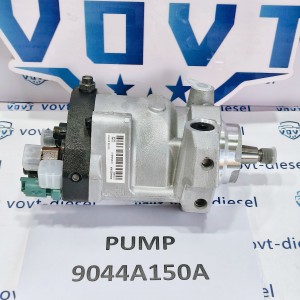
Diesel Fuel Injection Pump 9044A150A Engine Aut...
-

Good Price Diesel Pump Head Rotor 146405-1920 F...
-

High Precision Diesel Pump Plunger Barrel 2 418...
-

New Pressure Regulator Suction Pressure Valve C...
-

Diesel Engine Fuel Injection Pump 6CT for Cummi...


