
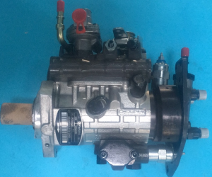
Diesel Fuel Injection Pump 0 460 424 211 0460424211 Engine Auto Engine Part


products description
| Reference Code | 0 460 424 211 |
| MOQ | 1 PCS |
| Certification | ISO9001 |
| Place of Origin | China |
| Packaging | Neutral packing |
| Quality Control | 100% tested before shipment |
| Lead time | 7~15 working days |
| Payment | T/T, Western Union, Money Gram, Paypal, Alipay, Wechat |
Working principle of oil pump
As an energy conversion device, the core of the oil pump is to change the internal volume through mechanical movement, converting mechanical energy into the pressure energy and kinetic energy of the fuel. Its working principle can be analyzed from three levels: basic theory, typical structural principle and dynamic working process:
1. Basic working principle: the core logic of the volumetric pump
All oil pumps work based on the principle of volume change and follow the following physical laws:
Volume change produces suction and discharge of oil: the volume of the sealed space increases or decreases periodically through the movement of components (plunger/gear/blade):
When the volume increases, negative pressure is formed, and the fuel is sucked into the pump under the action of atmospheric pressure;
When the volume decreases, the fuel is squeezed and discharged through the oil outlet.
Sealing performance determines efficiency: the matching clearance between components (such as the clearance between the plunger and the cylinder hole 0.005-0.01mm) must be strictly controlled to prevent high-pressure fuel leakage (leakage ≤5% is normal).
The essence of pressure establishment: the output pressure is determined by the system resistance, not the oil pump itself:
For example, the output pressure of the diesel common rail oil pump is 200MPa, which is essentially formed by the reverse thrust of the fuel injection resistance in the common rail pipe.
2. Principle disassembly of three typical oil pumps
(I) Plunger pump: the core power source of the high-pressure system
Take the radial piston pump of the diesel common rail system as an example (such as Bosch CP4 oil pump):
Structural composition:
Drive end: camshaft (driven by the engine crankshaft), roller frame;
Oil pumping mechanism: plunger (diameter 6-10mm), cylinder block (4-6 cylinder holes), oil distribution plate;
Control components: pressure regulating valve (PCV valve), pressure limiting valve.
Working process (single plunger cycle):
Intake phase: the cam valley drives the plunger to extend outward, the cylinder bore volume increases, the oil distribution plate oil suction port opens, and the fuel is sucked from the low-pressure oil circuit (pressure 0.5MPa);
Oil compression phase: the cam peak pushes the plunger to retract, the cylinder bore volume decreases, the fuel is compressed to 200MPa+, and the oil distribution plate outlet is connected to the common rail pipe;
Variable adjustment: the plunger stroke is changed by the swash plate angle (axial piston pump) or eccentricity (radial piston pump), and the displacement is adjusted (such as 0-100mL/r variable).
High pressure formation mechanism:
When the plunger diameter is 10mm, a thrust of 1000N can generate a pressure of 12.7MPa, and high pressure superposition is achieved by connecting multiple plungers in parallel (such as 3 plungers).
(II) Gear pump: a classic solution for low-pressure oil delivery
Take the electric gear pump of the automobile fuel tank as an example:
Structural core:
Driving gear (motor driven), driven gear (same number of teeth), the meshing clearance between the two is 0.05-0.1mm;
The pump body forms a sealed chamber, which is divided into an oil suction chamber and an oil pressure chamber.
Workflow:
When the gear rotates, the gear in the oil suction chamber disengages, and the volume increases to inhale the fuel (flow rate 30-100L/h);
The fuel is brought to the oil pressure chamber along with the gear tooth groove, and the fuel is squeezed when the gear meshes, and the pressure rises to 0.3-0.5MPa;
Pulsation suppression: The pump body has a relief groove to relieve the pressure shock when the gear meshes (noise ≤70dB).
(III) Vane pump: the best choice for low pulsation flow
Take the vane pump of machine tool lubrication system as an example:
Unique structure:
Rotor (with radial grooves), vanes (6-12 blades, slidable), stator (elliptical inner surface);
The spring (or centrifugal force) on the top of the vane ensures a close fit with the stator.
Principle and characteristics:
When the rotor rotates, the vanes extend outward under the action of centrifugal force, forming a sealed cavity with the stator, rotor, and oil distribution plate;
The volume of the sealed cavity changes periodically with the rotation of the rotor:
The volume at the long axis increases to absorb oil, and the volume at the short axis decreases to pressurize oil;
The double-acting vane pump absorbs and discharges oil twice per rotation, and the flow pulsation rate is less than 5% (better than the gear pump).
3. Key mechanisms in dynamic working process
Oil suction capacity limitation:
The oil pump suction height is generally ≤1m, otherwise cavitation will occur due to the fuel vapor pressure (such as gasoline vapor pressure 70kPa at 40℃);
Solution: Electric oil pump is placed in front (such as oil-immersed installation in the fuel tank), or a pre-pressure pump (gear pump in front of the diesel engine high-pressure oil pump) is set.
Balance of pressure and flow:
Take the automobile high-pressure oil pump as an example:
When the engine load increases, the ECU controls the PCV valve to reduce the opening, the plunger oil pressure stage is extended, the output flow increases (such as from 50mL/stroke to 150mL/stroke), and the pressure is maintained at 15-20MPa;
When the system pressure exceeds the set value (such as 25MPa), the pressure limiting valve opens to relieve pressure to prevent the common rail pipe from bursting.
Idling protection mechanism:
When the gear pump and vane pump are idling (without fuel cooling), the frictional heat generated by the components may cause the temperature to exceed 120℃ and damage;
Design: The electric oil pump has a built-in thermistor, and the speed is reduced when the temperature exceeds 80℃; the plunger pump is lubricated by fuel and allows short-term idling (≤30 seconds).
4. Principle optimization for different application scenarios
Scenario Principle optimization direction Example
Diesel engine common rail system Multi-plunger parallel + variable control Bosch CP4 oil pump 6 plunger design, pressure fluctuation ≤±2%
New energy vehicle electric drive Brushless motor + centrifugal impeller Tesla oil-cooled motor oil pump uses a centrifugal pump with an efficiency of 90%+
Engineering machinery hydraulic system Constant power control + load sensitivity Excavator oil pump automatically adjusts displacement according to engine speed to avoid overload
5. Impact of key technical parameters on the principle
Volume ratio (ηv): actual flow / theoretical flow, plunger pump ηv≥90% (due to small gap), gear pump ηv≈80% (meshing gap leakage);
Speed (n): Electric oil pump n=3000-8000rpm, too high speed leads to insufficient oil suction (when the cavitation threshold n≥6000rpm, the diameter of the oil suction port needs to be increased);
Viscosity (μ): The best fuel viscosity is 0.8-3cSt, and the viscosity is too high (such as diesel at low temperature μ>5cSt) will lead to increased oil suction resistance and increased pump load.
6. Technological development to innovation of principles
Electro-hydraulic hybrid pump:
Integrated motor and hydraulic pump, the motor drives the oil pump at idle speed to reduce engine energy consumption (such as Mercedes-Benz 48V system oil pump);
Digital hydraulic pump:
Use servo motor to control plunger stroke to achieve precise pressure/flow adjustment (response time <5ms), applied to intelligent agricultural machinery;
Magnetic drive pump:
No shaft seal design, drive impeller through magnetic field coupling to avoid fuel leakage (applicable to LNG engine fuel pump).
From ultra-high pressure injection of diesel engines to electro-hydraulic integration of new energy vehicles, the evolution of oil pump principles has always revolved around "energy conversion efficiency" and "control accuracy". For example, the latest common rail oil pump has achieved precise control of a single injection volume of 0.5mm³ (equivalent to 5 times the volume of a hair diameter), which is the ultimate application of principles such as volume change, pressure establishment, and fluid mechanics.
Products categories
-
Fuel Pump BHF4AW100007 For CHAOCHAI CY4100ZLQ O...
-
Diesel Fuel Injection Pump BH4P120 Engine Auto ...
-

High Quality Fuel Injector Pump 9521A320T For P...
-

Diesel Fuel Injection Pump 476-8769 For CAT Eng...
-

High Performance Diesel Fuel Injection Pump 0 4...
-

Diesel Fuel Injection Pump 0 445 010 159 044501...


